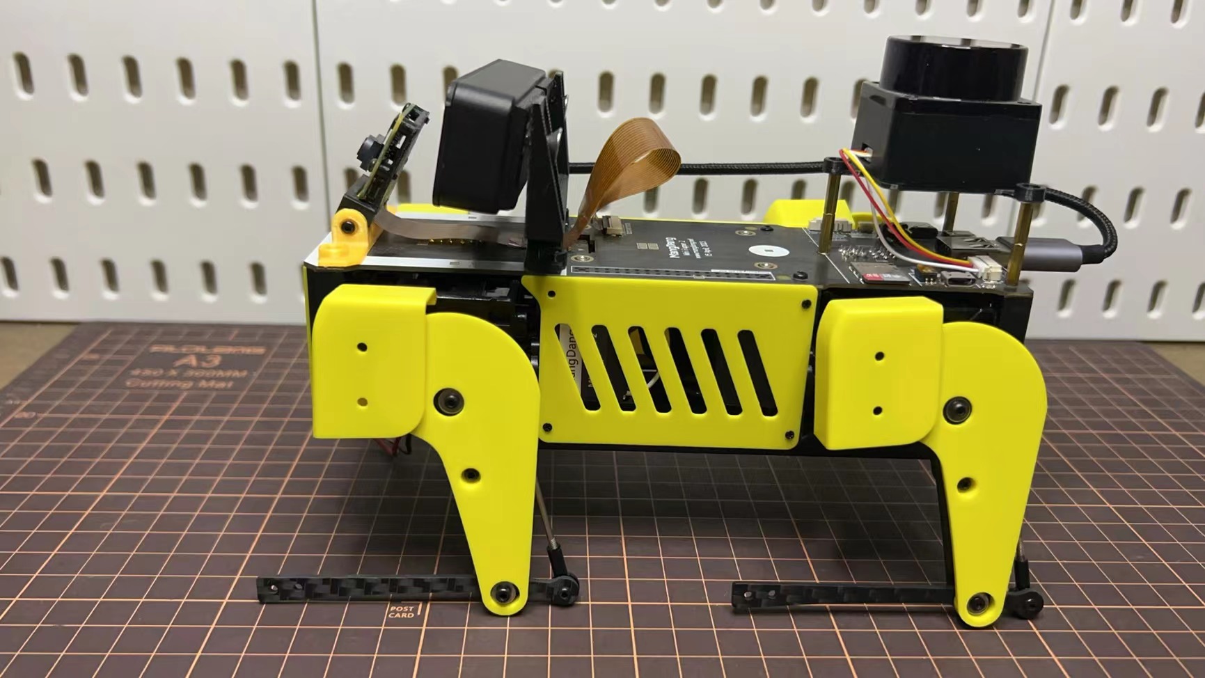
ミニぷぱ2の組み立て
1. Standard Kit Main Parts Assembly
Step 1 準備
全部品一覧です。

Step 2 底板の組み立て
M2 x 5mmのネジを使用して4本の脚を底板に接続します。

Step 3 上部PCBボードの組み立て
四脚の接続ワイヤーを上部PCBボードに挿入します。LCDスクリーンケーブルをPCBボードに接続します。向きに注意してください。

Step 4 電源ラインの調整
PCBボードの電源ラインを底板の穴に通します。

Step 5 スピーカーの組み立て
M2 x 5mmのネジを使用してPCBボードと底板を固定します。

2. Cover Assembly
以下のビデオクリップを参照してください。
Step 1 本体のサイドパネル
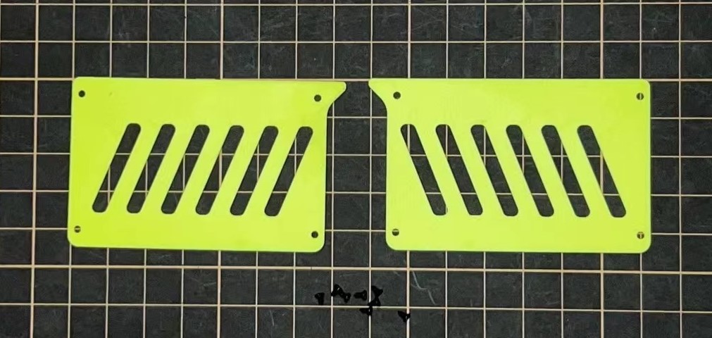
Step 2 もものカバー
M2x10mmの皿ネジを4本使用します。
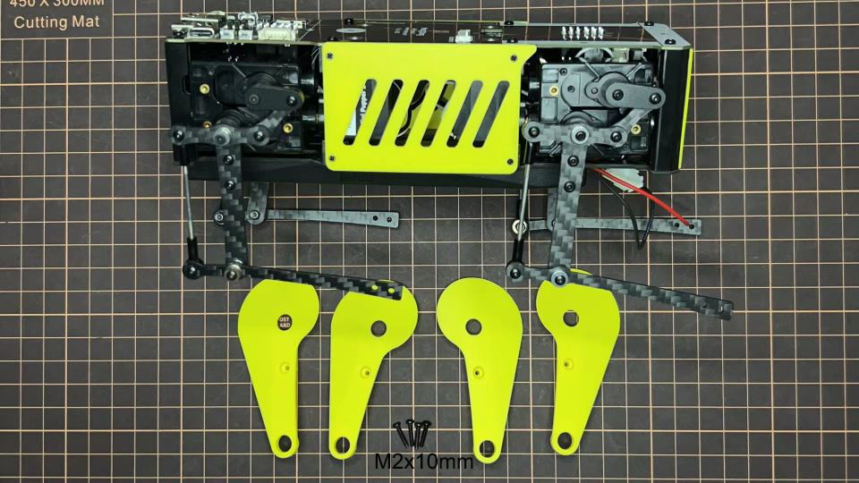
Step 3 ショルダー
まずネジだけを差し込み、その隙間にショルダーパーツを差し込みます。ショルダーパーツの穴に2mmの六角ドライバーを差し込んでネジを締めます。
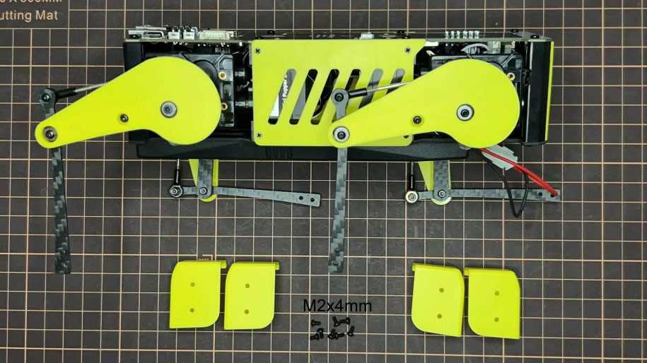
Step 4 足先
足先を取り付けます。
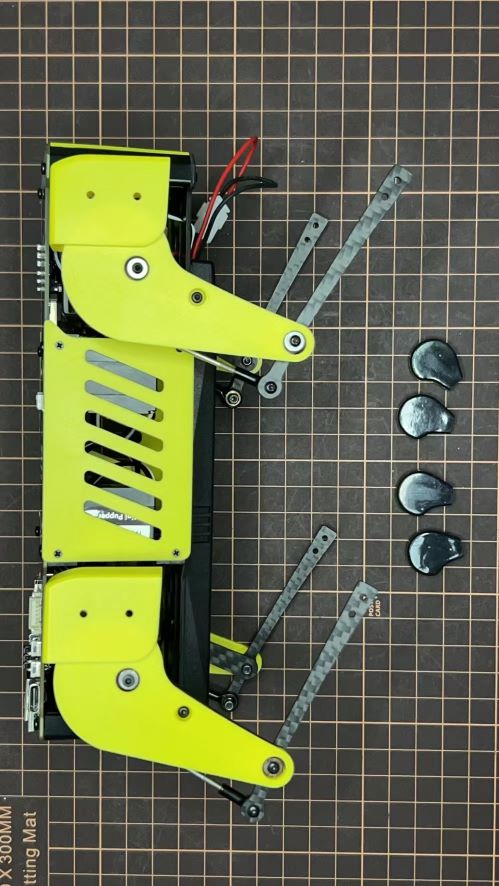
完成!
3. Add-On Assembly
Step 1 Lidar
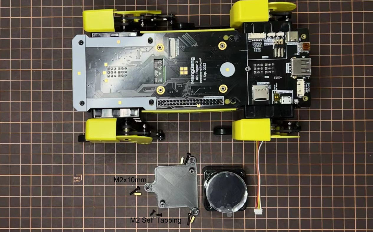
If you order the Lidar, the 3D-printed Lidar holder and custom cable will be shipped together. You can also print the holder by yourself using the STL files
Connect the 3 holders to the 3D-printed part; Connect the custom cable to the Lidar connector on the PCB board; Fix the 3D-printed part on the PCB board; Connect the custom cable to the Lidar module and fix it using the self-tapping screws.
Step 2 カメラ
ミニぷぱ2は、1つのPiカメラまたはOpenCV OAK-D-Liteカメラモジュールもサポートしています。次のファイルを使用して、ホルダーを自分でプリントすることもできます。Mini Pupper 2 STLファイル