Assemble Mini Pupper 2
目次
This is the video clip for the complete kit, please refer to the below sections for detailed steps.
Please also refer to Mini Pupper 2 Fusion 360 CAD model: https://a360.co/485n8mP
1.イメージを焼きこむ
ツール
キットに同梱されている工具の他に、組み立てには以下の物が必要です。
USB キーボード
USB マウス
PC
microSDカードリーダ
HDMI ディスプレイ
micro HDMI ケーブル
USB充電器
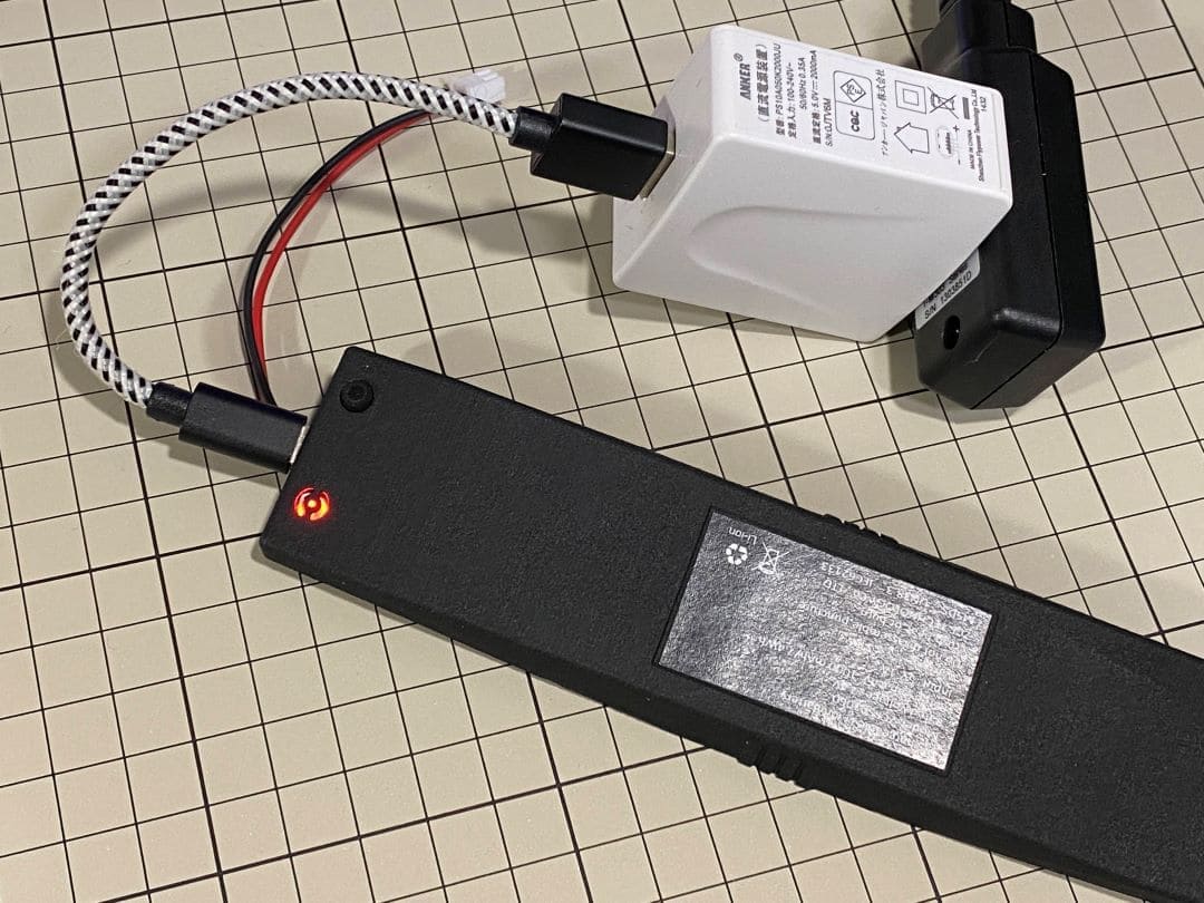
Step 1.1充電
準備としてバッテリーをUSBで充電しておきます。USBの差込口は写真を参照。ミニぷぱに取り付けたままでも充電できます。
LEDライト:緑は十分な力があることを表し、赤は充電必要を表しています。
5V/1Aアダプタの使用がお勧めです。5V/2Aのアダプタを使用している場合、バッテリーチャージャーICは自動的に電流を1Aに変更します
Step 1.2 イメージファイルのダウンロード
You can download the pre-built image files from Mini Pupper pre-built images
※ “xxx_stanford**.img” means the image is for Ubuntu 22.04 version.
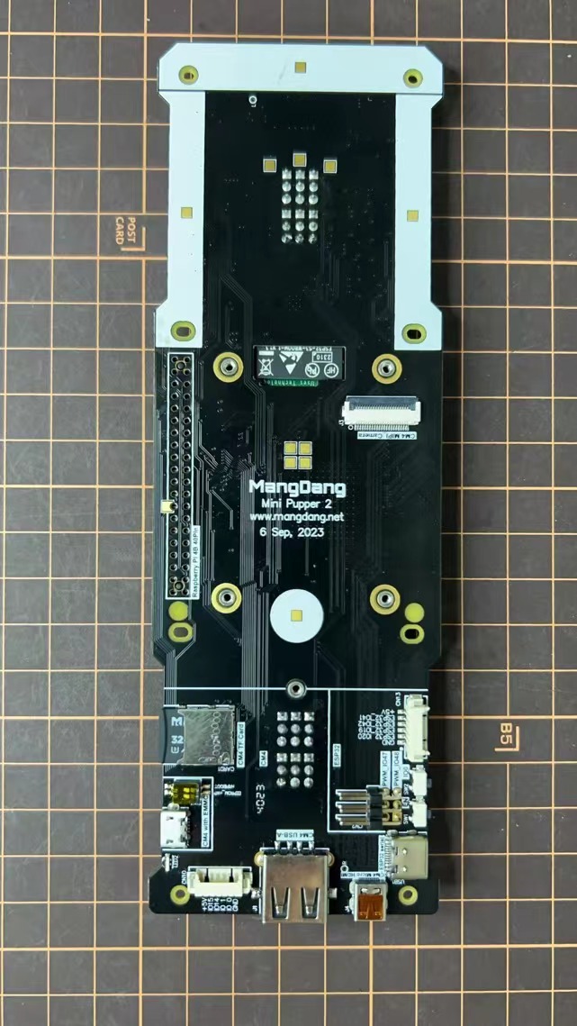
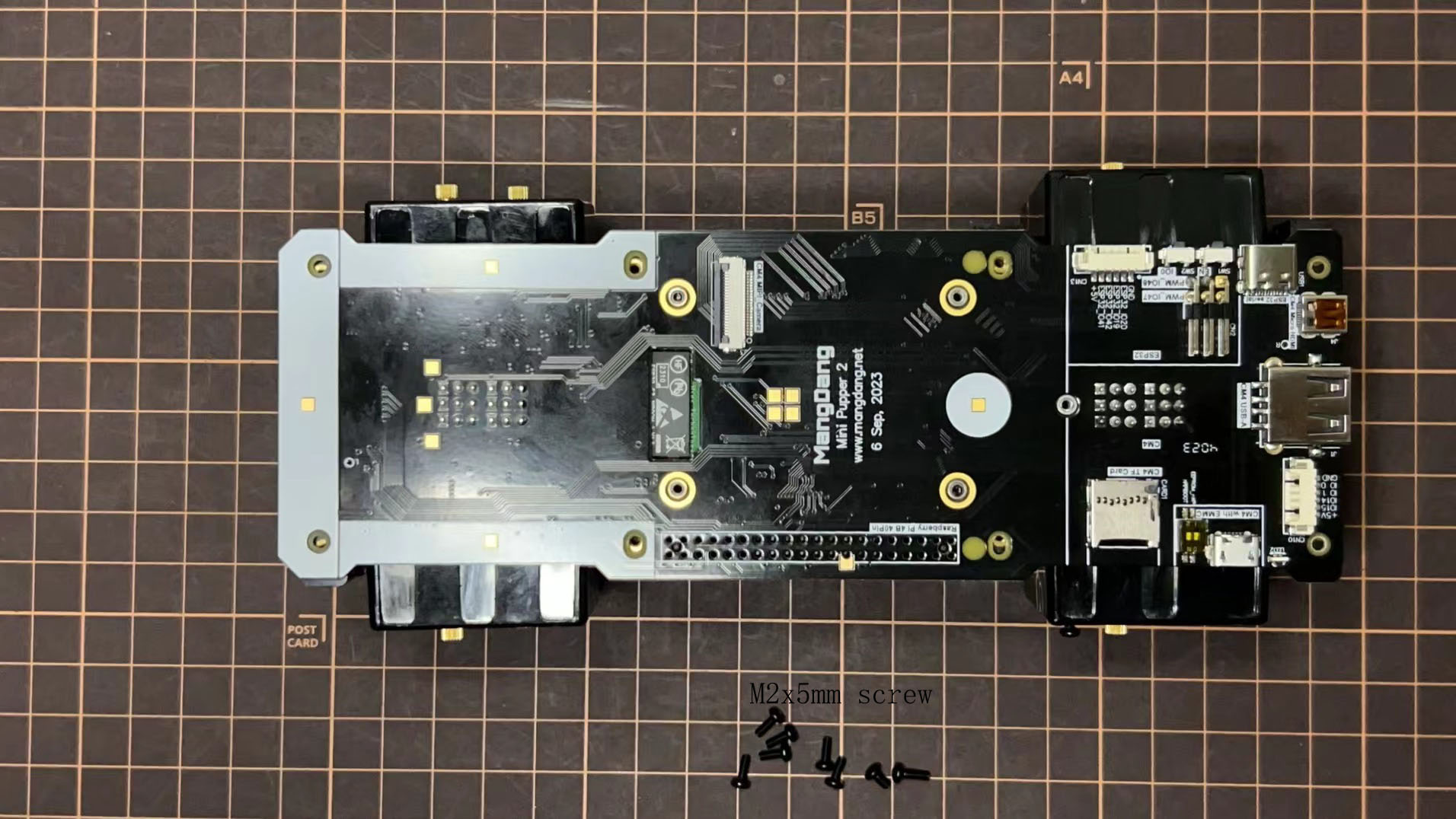
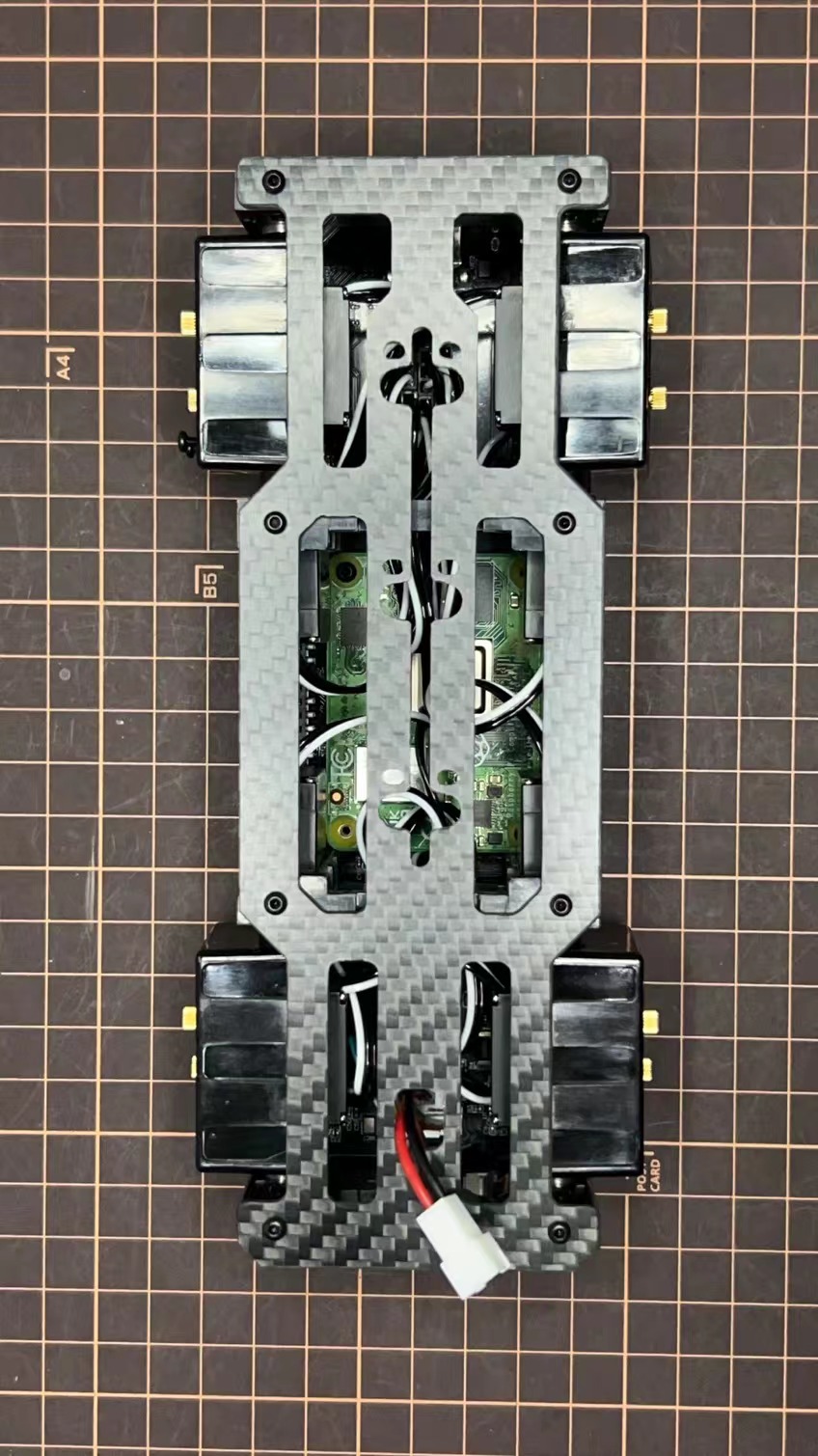
The picture below is the custom carry board.
Step 1.3 Write the image into a microSD card
Insert the microSD card into your PC's SD card reader and write the image. We recommend the image creation tool balenaEtcher or Win32DiskImager as it is easy and reliable. Please take a look at the official manual. It may take a while to complete.
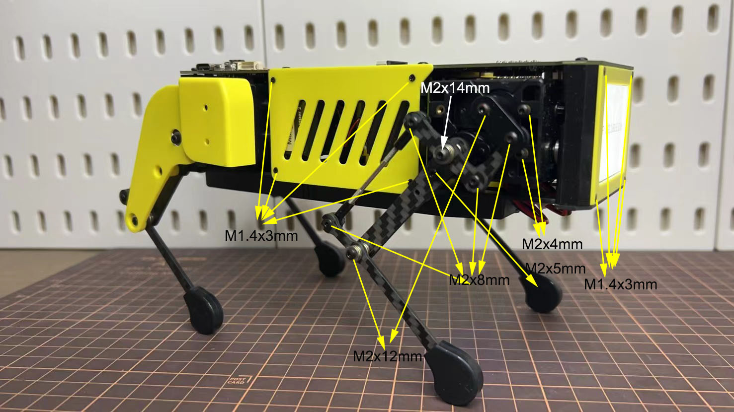
2. ネジの配置
写真はネジの位置を簡単に示しています。
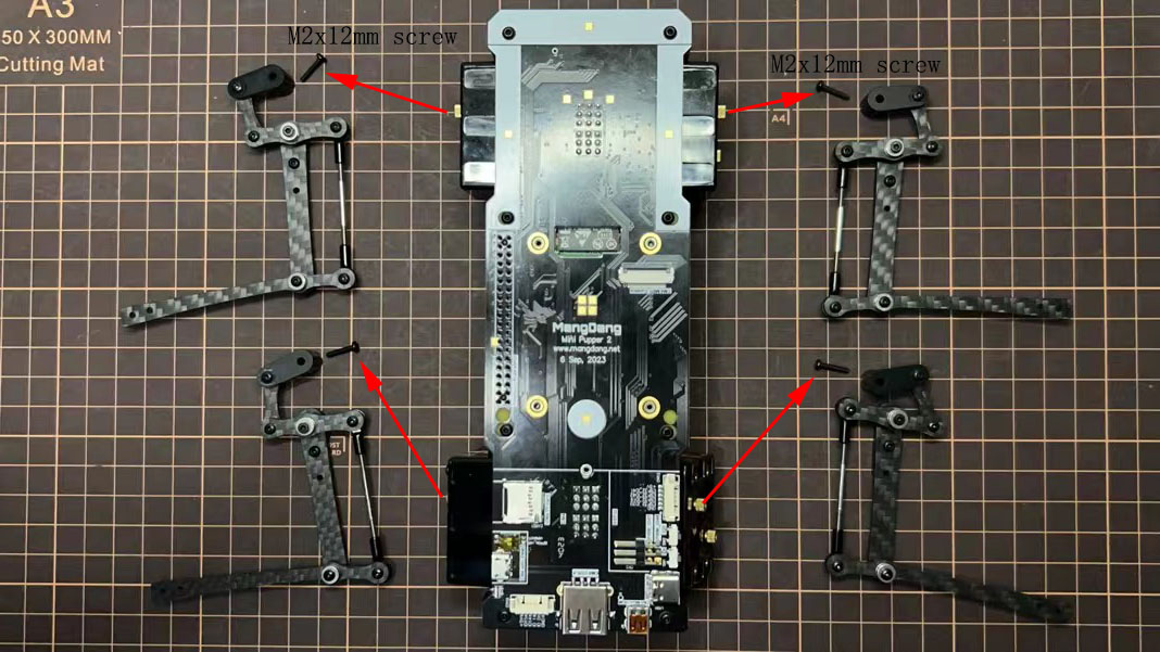
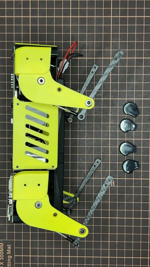
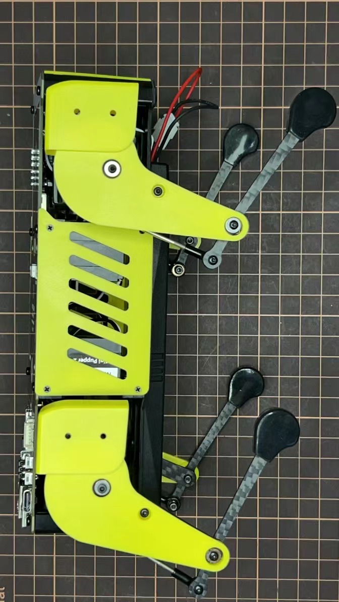
3. 脚の組み立て
以下の動画をご参照ください。
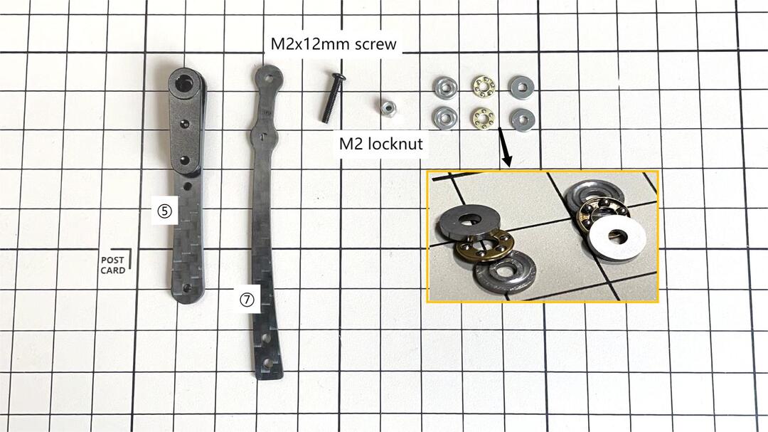
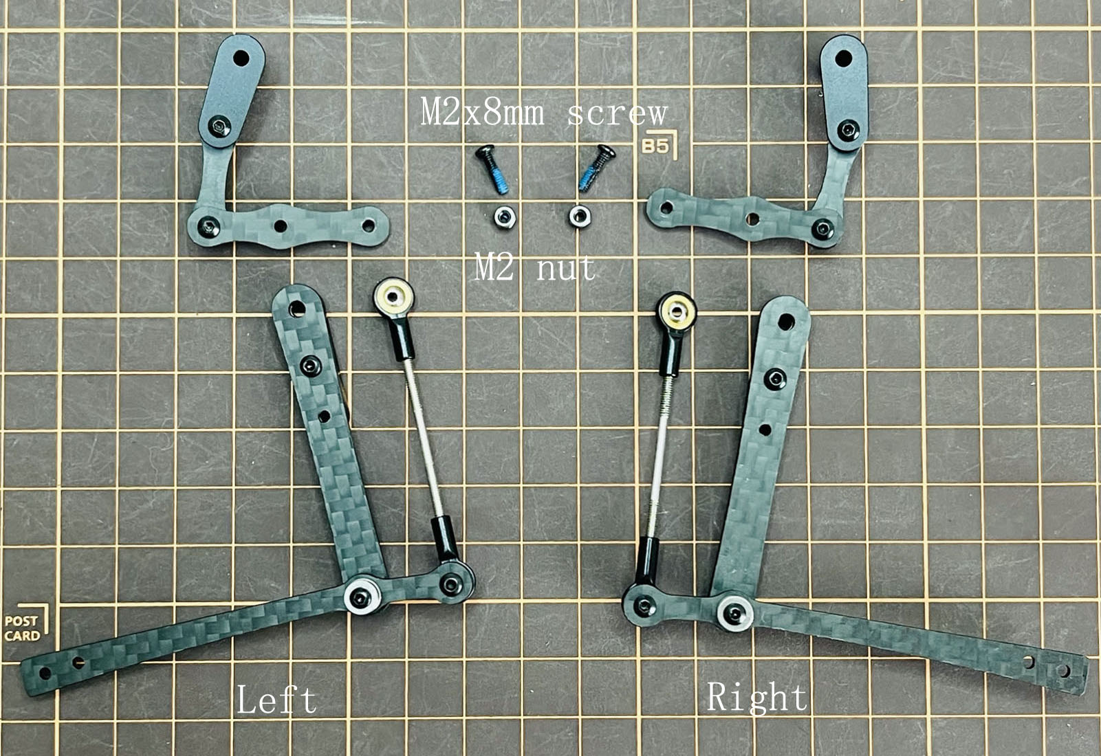
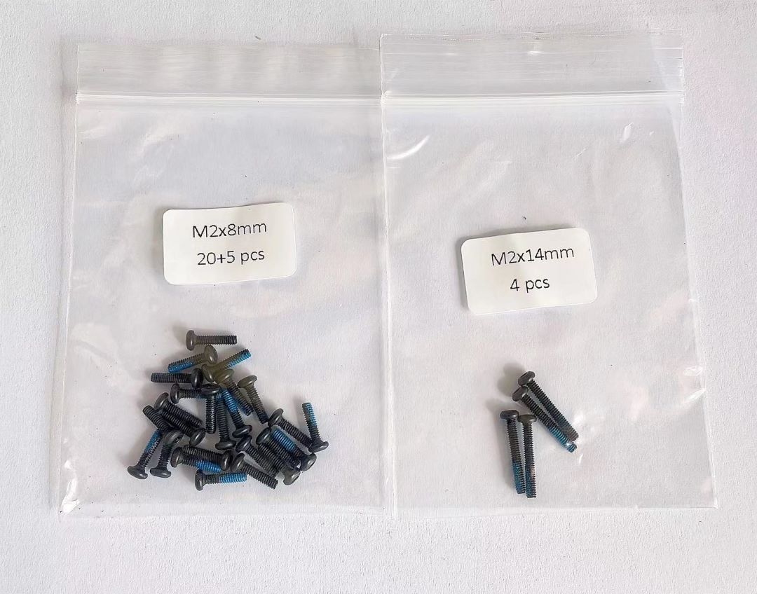
使用するボルト
M2x5mm 2x4=8 ①+②, ⑤+⑥
M2x8mm 3x4=12 ②+③, ④+⑦, ③+④
M2x12mm 1x4=4 ⑤+⑦
M2x14mm 1x4=4 ③+⑤
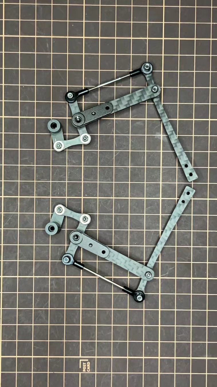
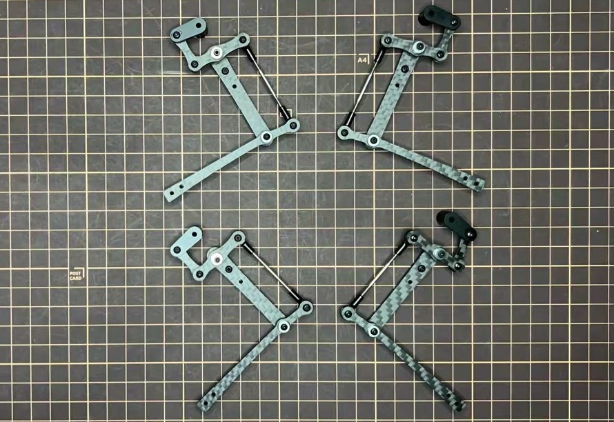
Step 3.1 片脚
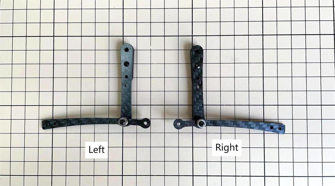
脚を組み立てるとき、左側は前後セットで同じ形の足2つ、右側も同様で、併せて足を4コ組み立てます。下記は右側の前後セットを例に詳しく説明します。
説明動画は下記のリンクをご参照ください。https://youtu.be/Ut7UnS3CTZs
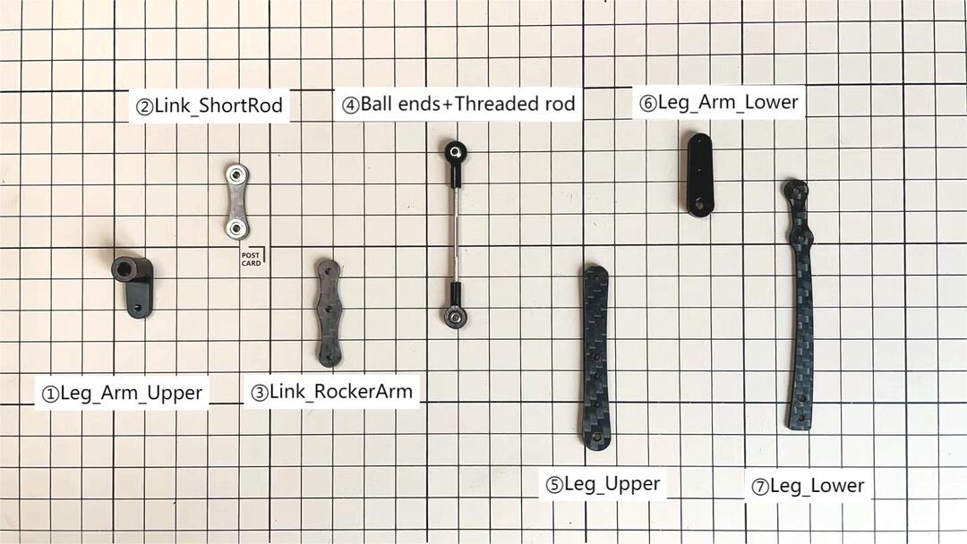
説明の便宜上、以下のようにパーツに番号を振りました。
①と②の組み立て
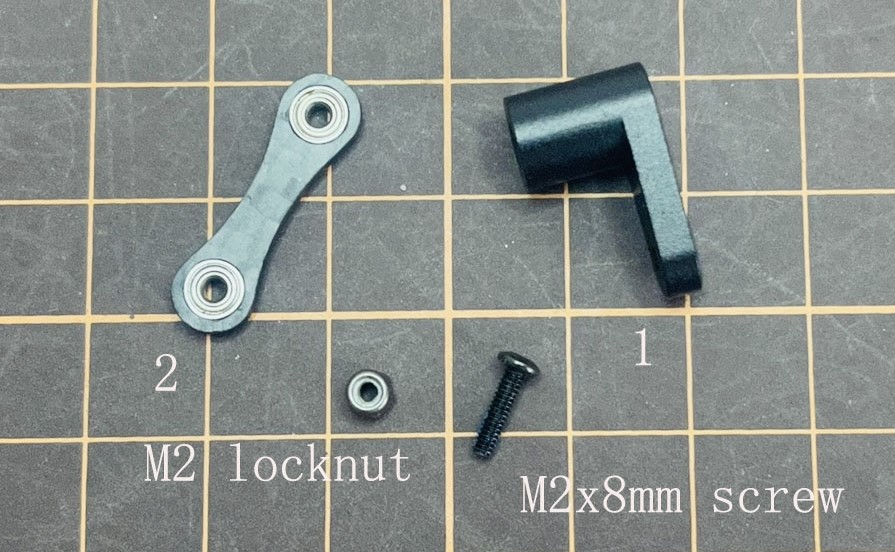
The two sides of bearings inside ② are different.
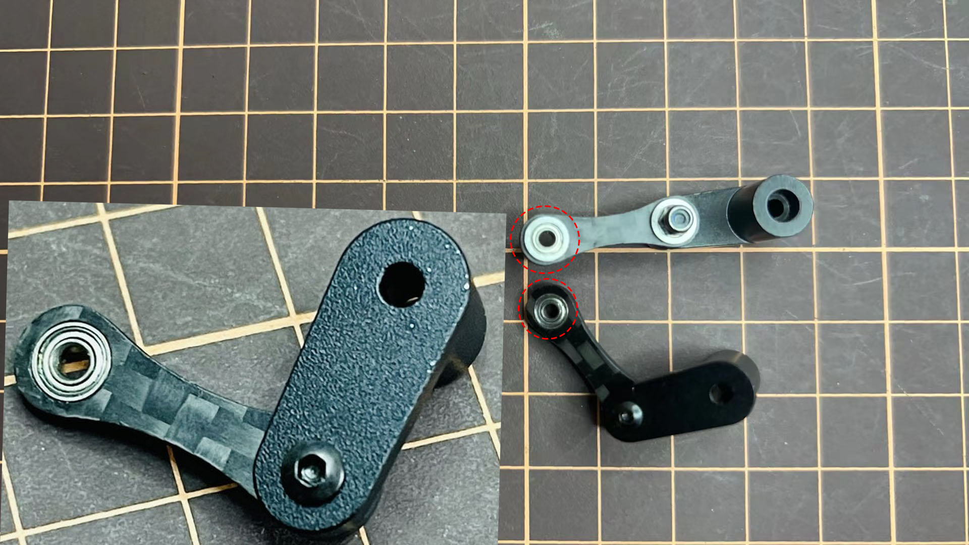
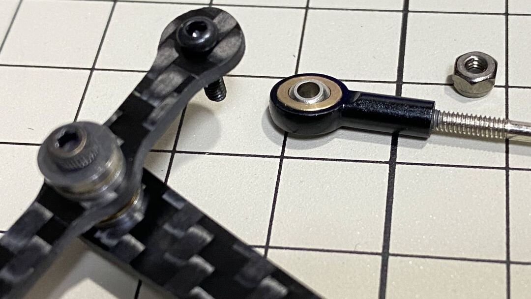
②と③の組み立て
M2x8mm のボルトを1つと M2 Locknutを使用します。ボルトを③の下から上に挿し、②を通し、ナットで締めます。③の部品の向きには気をつける必要があります。真ん中の穴の位置を良く見ましょう。
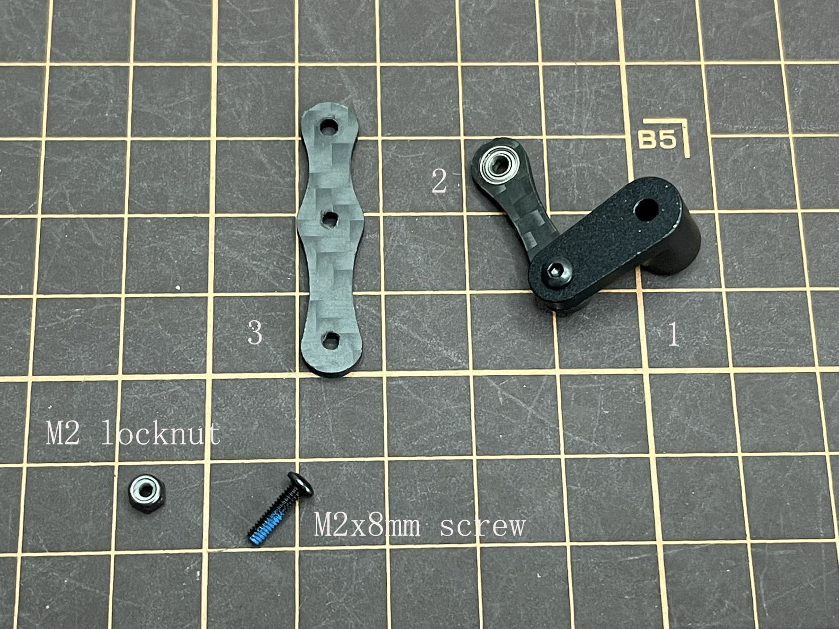
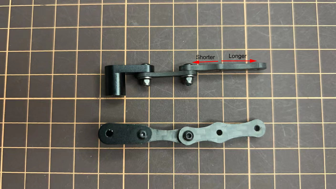
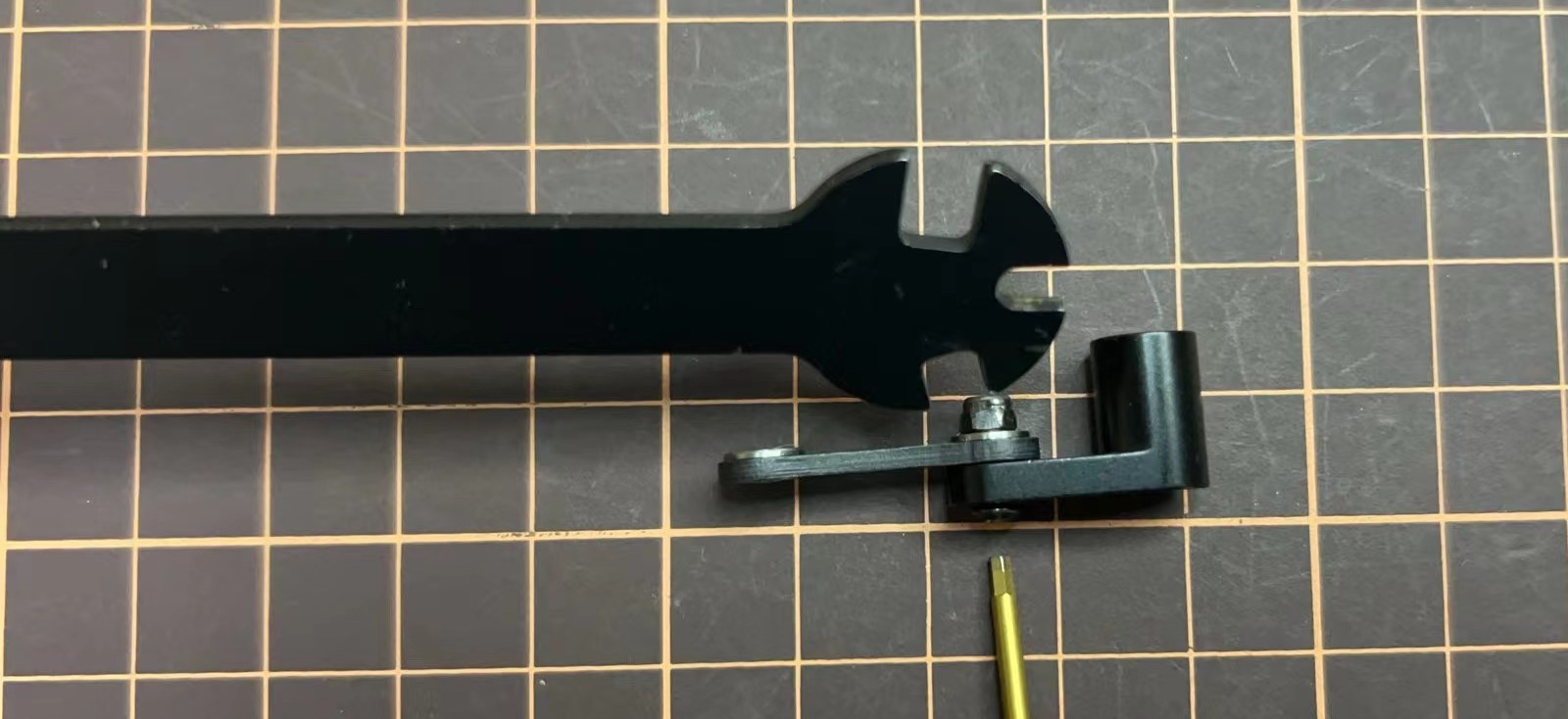
④の長さの調整
④の長さが⑤と一致している必要があります。長さを調整するとき、M2x14mmなどの長いボルトを2本使うと、長さが一致しているか確認しやすいです。長さの調整が完了したら、これらはすべてバラしましょう。
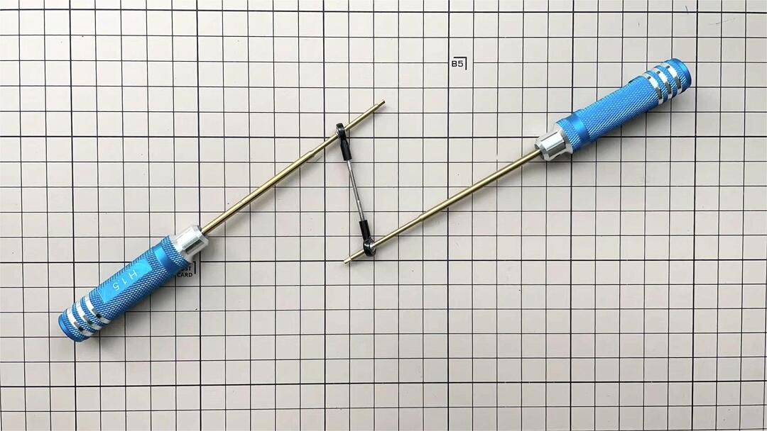
組み立て中回しづらい場合、ドライバーなどの工具を使ってまた試してみてください。
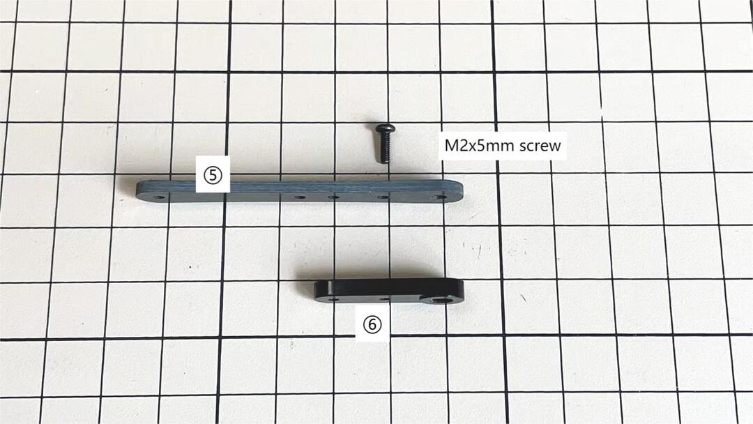
⑤と⑥の組み立て
下図のように、M2x5mm のネジを1コ図中の部品 ⑤ と部品 ⑥ のところに差し込み、締め付ける。
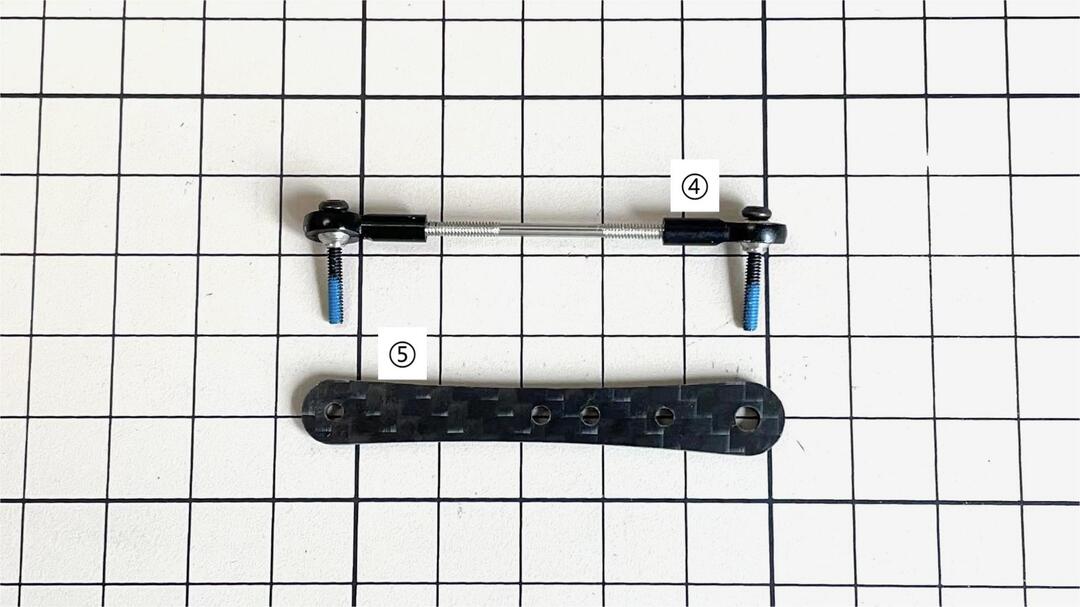
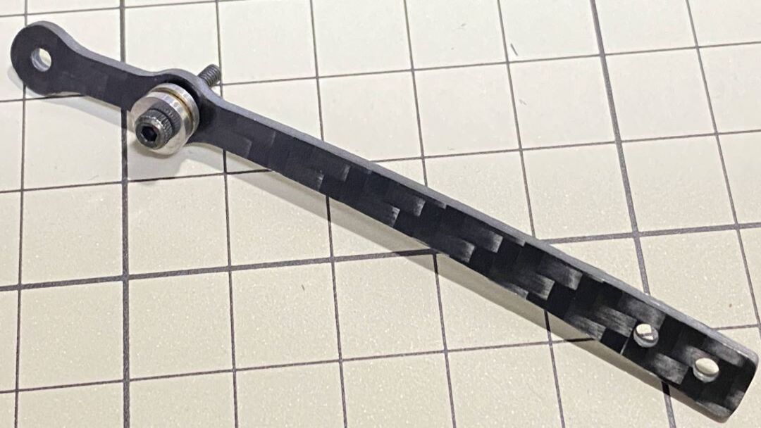
部品 ⑤ と ⑦ を結合
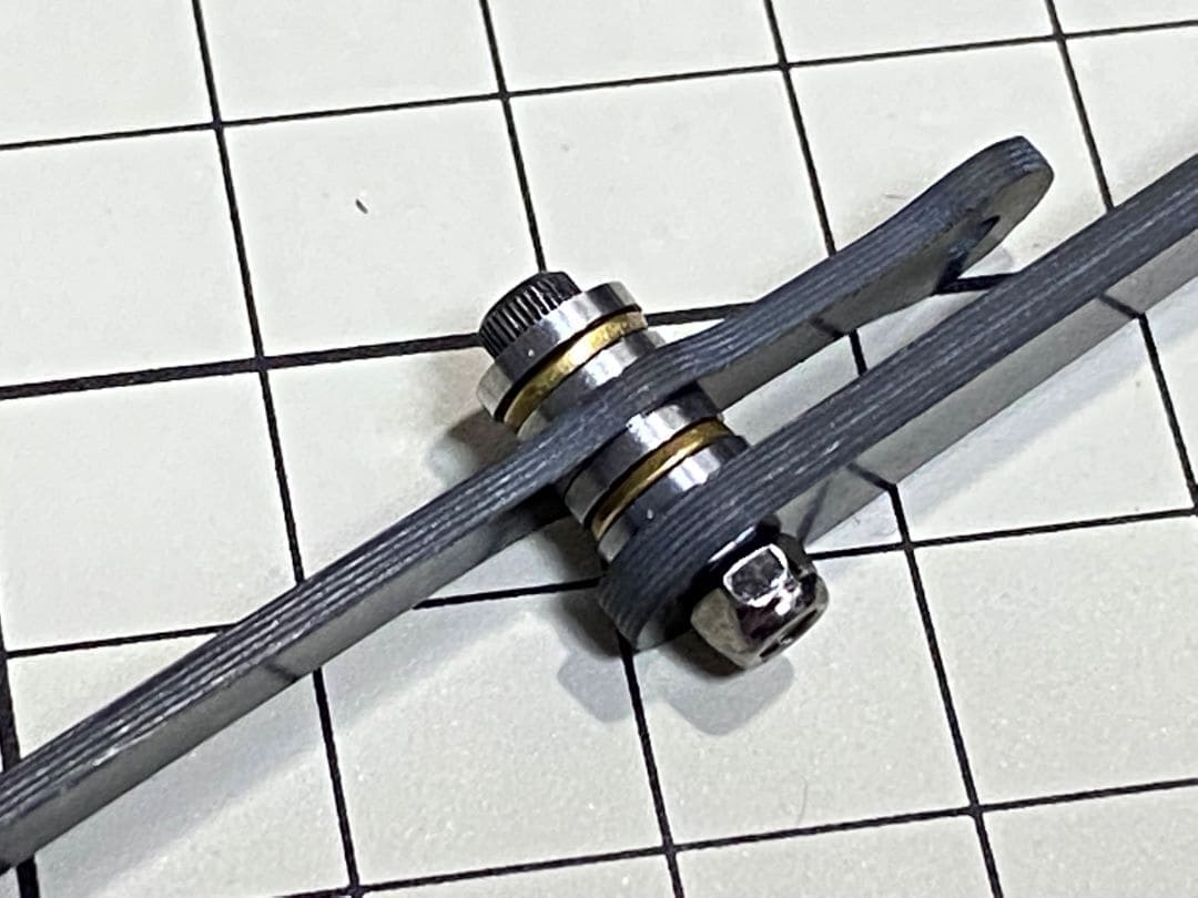
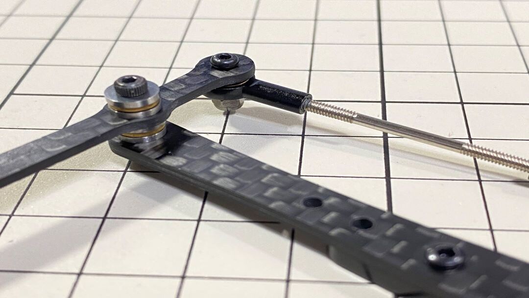
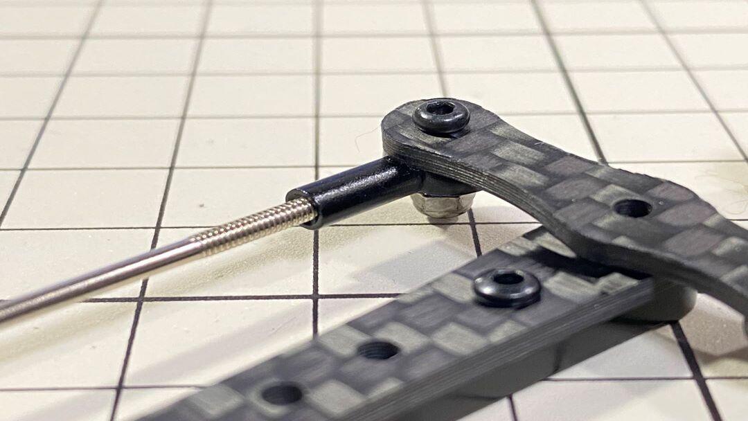
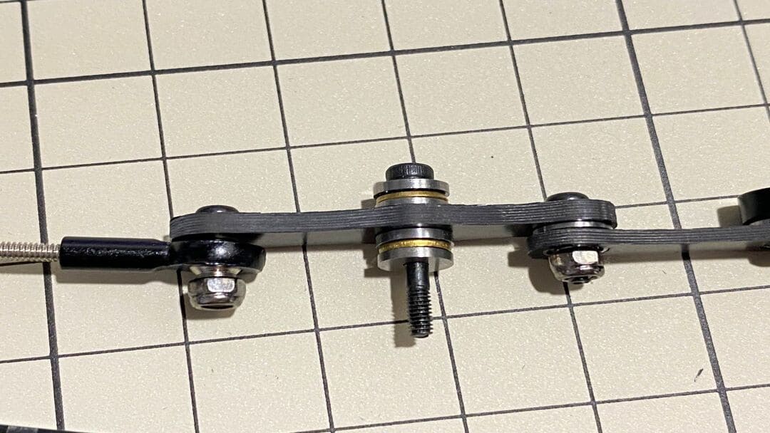
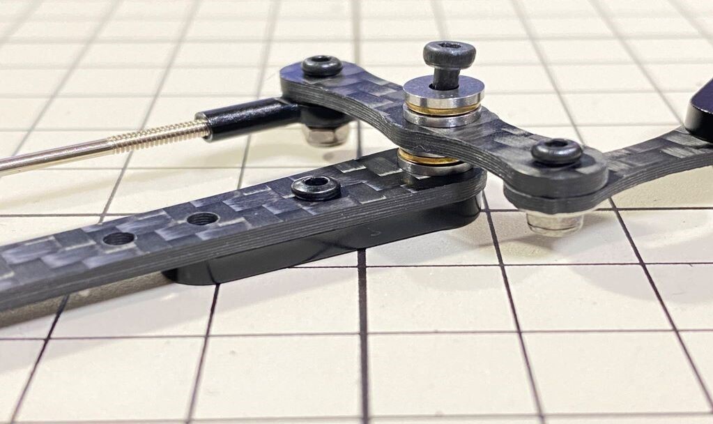
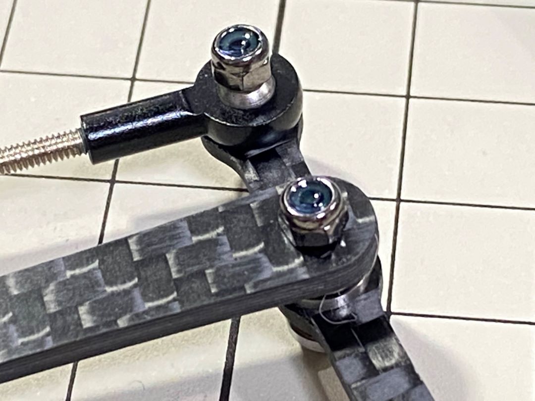
M2x12mmのボルトとM2 locknutとボールベアリング2組を使用します。ボールベアリングは3つの部品から成り立っており、上下の部品は溝がある方を内側に向けて、真ん中の部品をはさみます。まずボールベアリングにボルトを通します。次に⑦の穴にボルトを挿します。このとき⑦の反っている方向を見て、向きを間違えないように気をつけます。次にもう一つのボールベアリングをボルトに通します。最後に⑤をボルトに通してナットで締めます。
部品 ④ と ⑦ を結合
M2x8mmのボルトとM2ナットを使用します。⑦にボルトを挿し、④を通したら、ナットで締めます。④の表裏の向きはどちらでも大丈夫です。
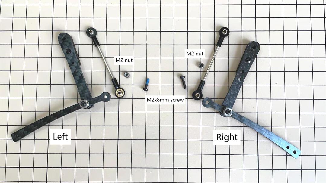
左右セットの足
部品 ③ と ④ を結合
M2x8mmのボルトとM2ナットを使用します。③にボルトを挿し、④を通したら、ナットで締めます。
左右セットの足
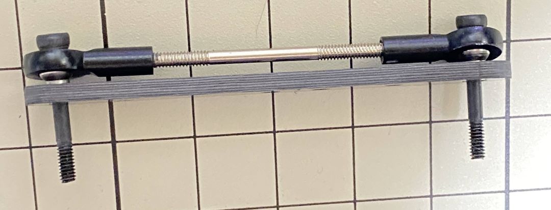
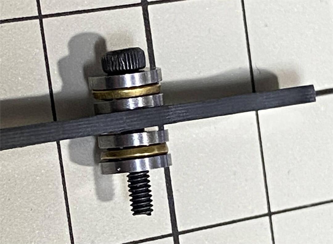
部品 ③ と ⑤ を結合
M2x14mmのボルトとボールベアリング2組を使用します。ボルトをベアリング、③、ベアリング、⑤の順で通します。ボルトは固定されていませんが、次工程でサーボに取り付ける際にボルトを締めます。
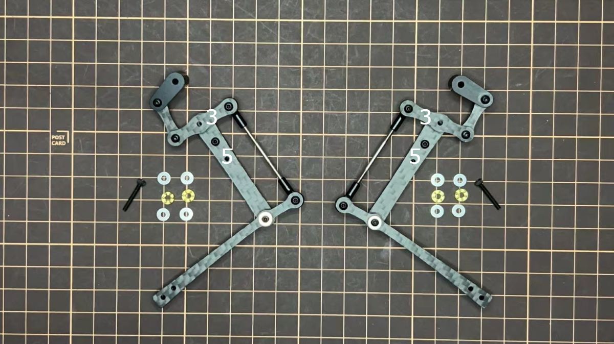
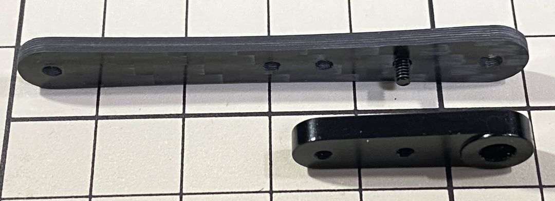
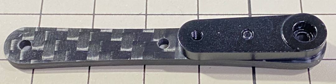
脚部の仕上げ
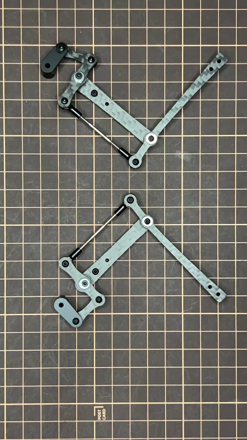
これで右側の脚が一本完成しました。色んな角度から見れるように写真を貼っておきます。左側は右側と線対称になるように組みます。
裏
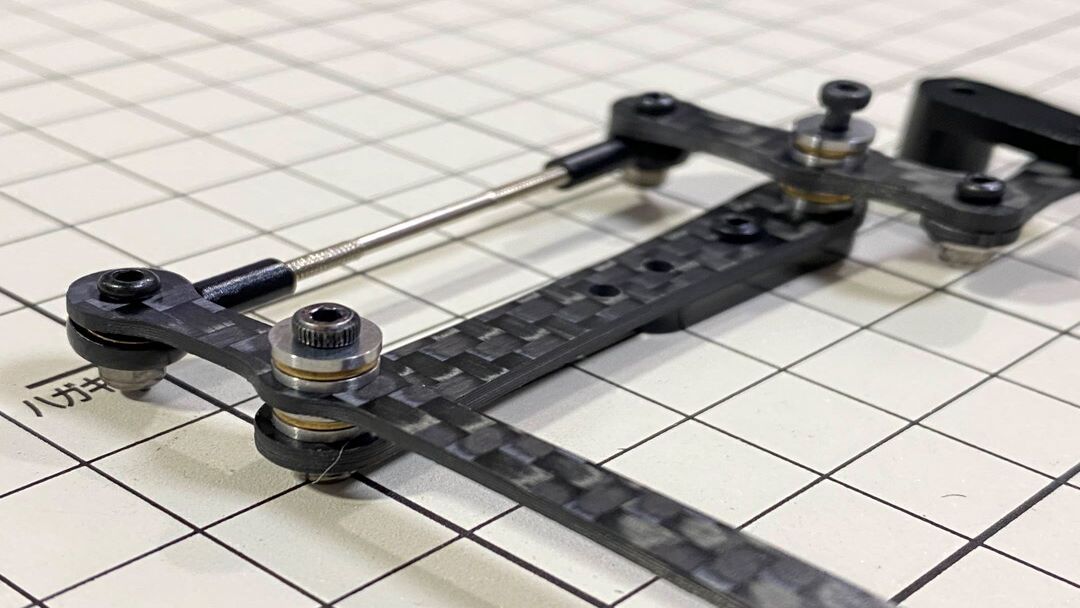
Step 3.2 前足と後ろ足
Step 3.3ロックタイト
After Mini Pupper run sometime, some screws or nuts will loose, you have to check and tighten them if needed. It's helpful to understand how it works.
※ We don't recommend new users to use the Loctite at first, you can use it after you have much background.
ロックタイトはナットの緩みを防止しますが、緩みに気づいたときに締めれば良いので必須ではありません。
また、下の写真のように接着剤をつけたネジもあります。
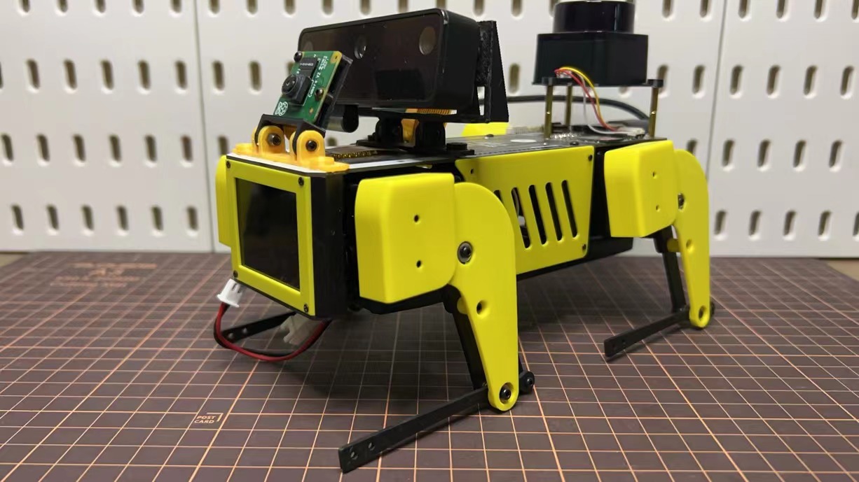
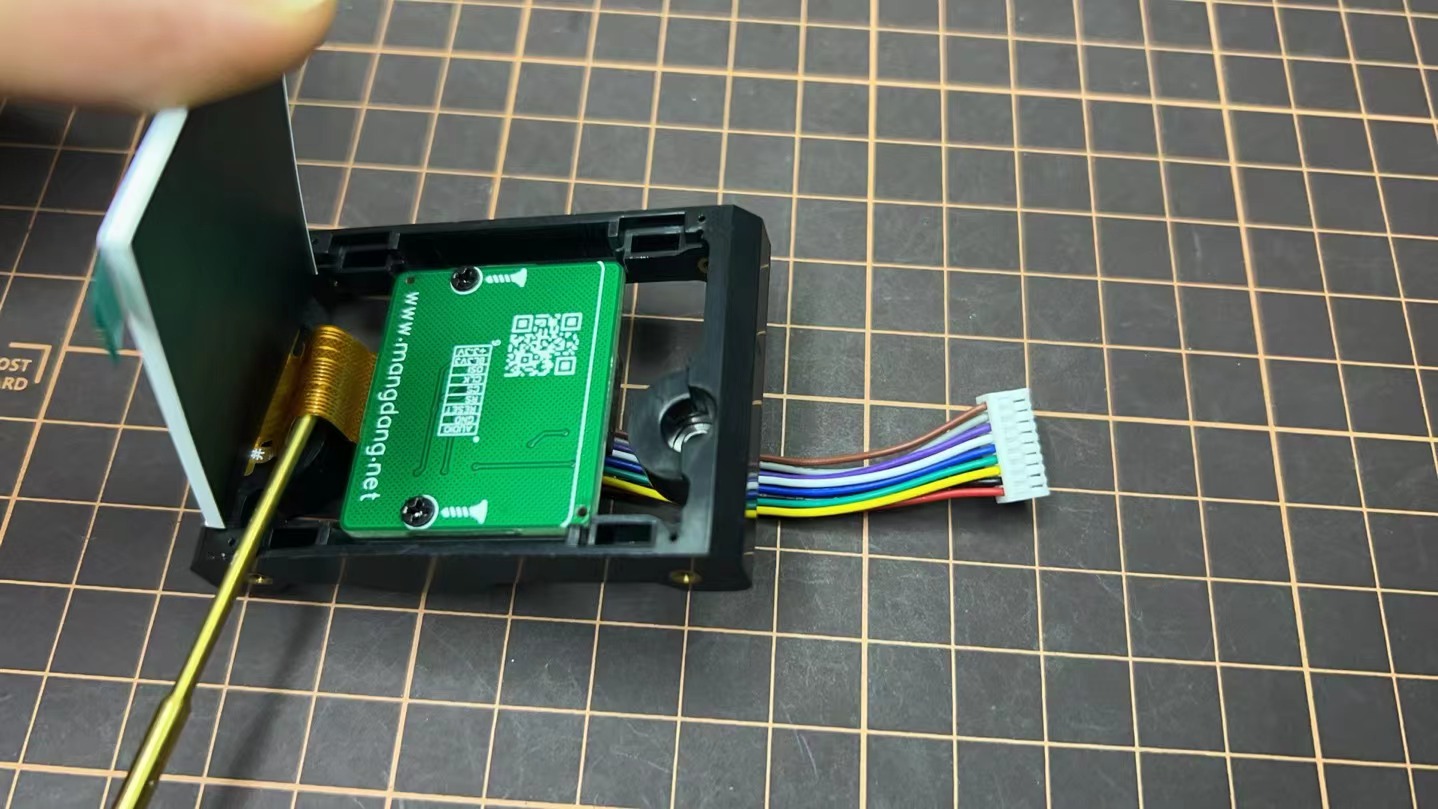
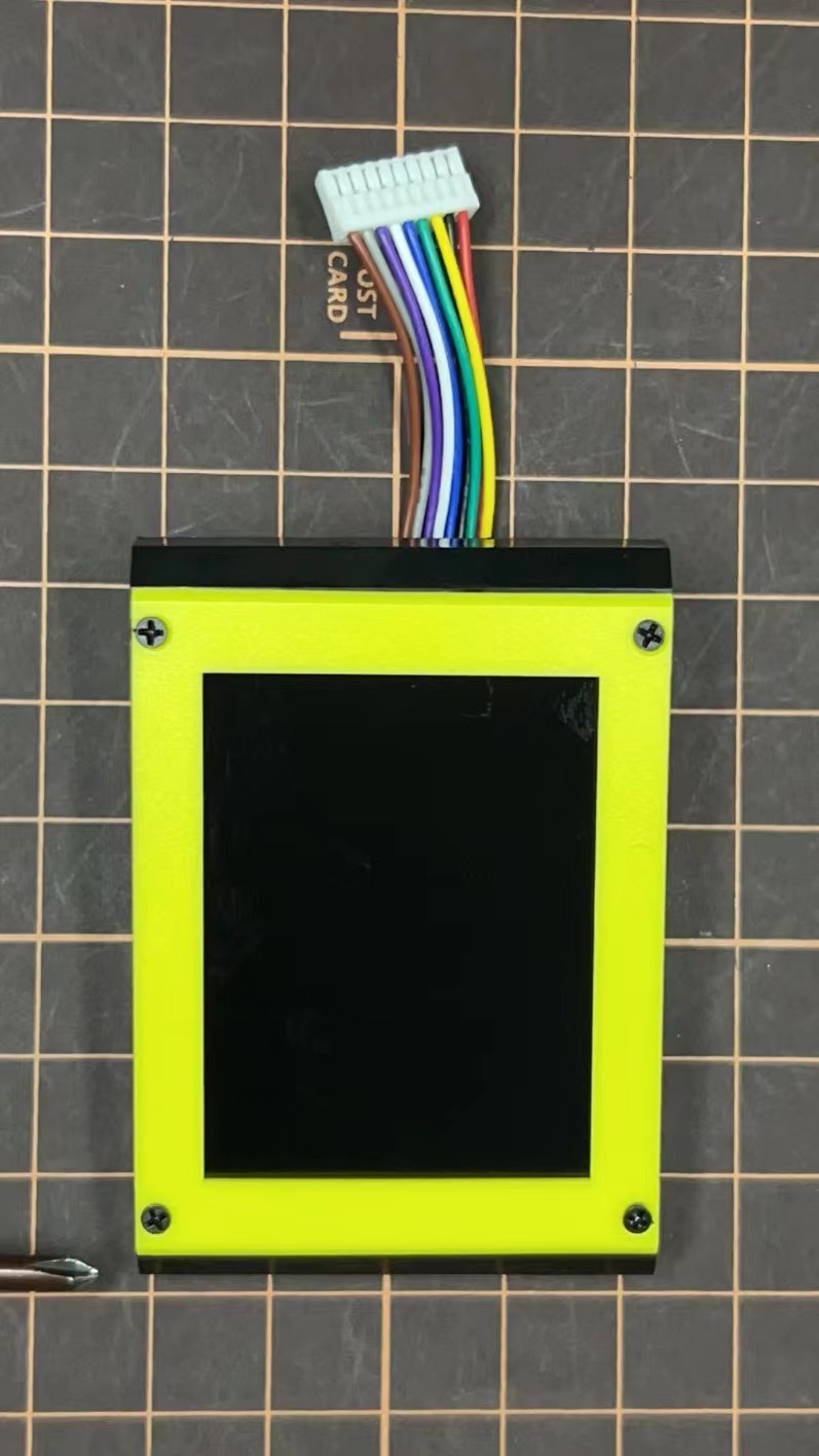
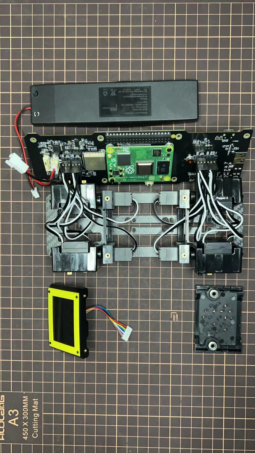
4. Display and Frame of face
Remove the protective sheet for the display. Fold the thin flexible cable at the edge of the display. Attach the board and the display to the main unit.
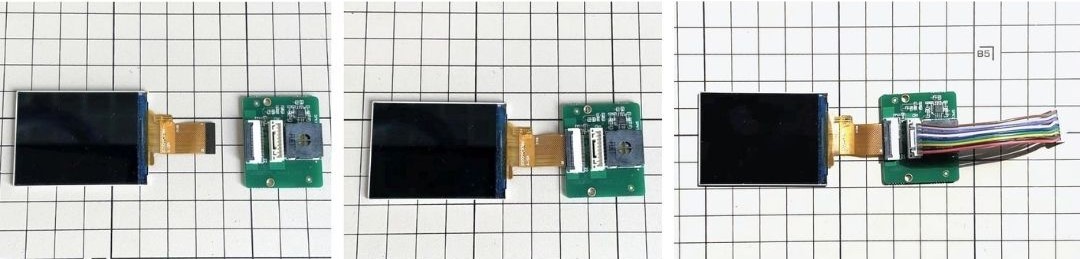
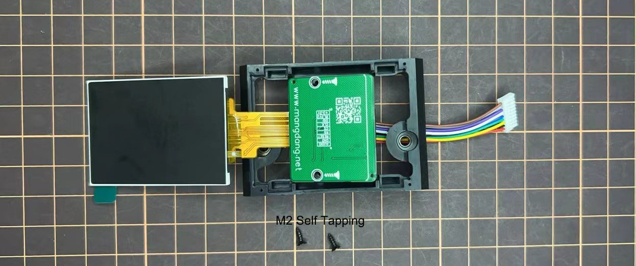
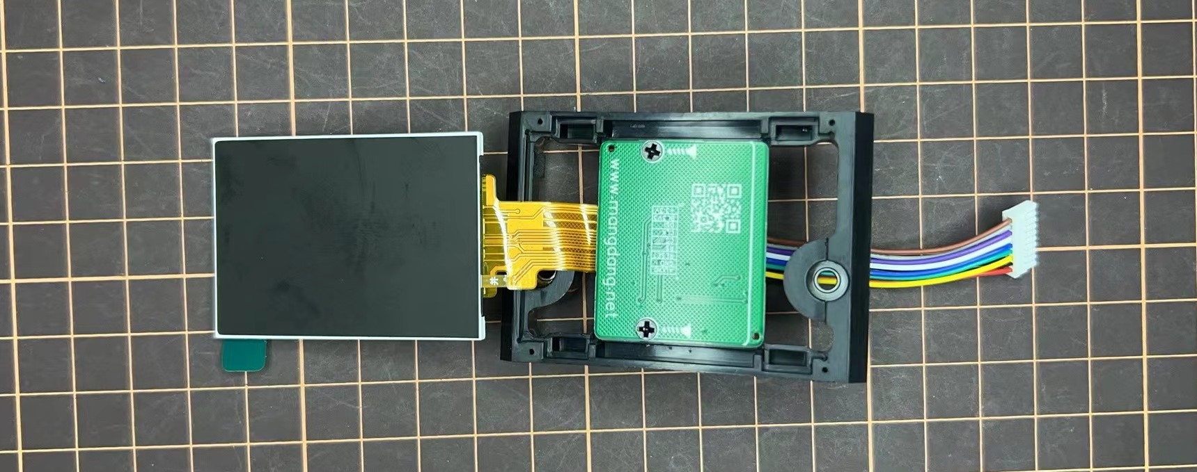
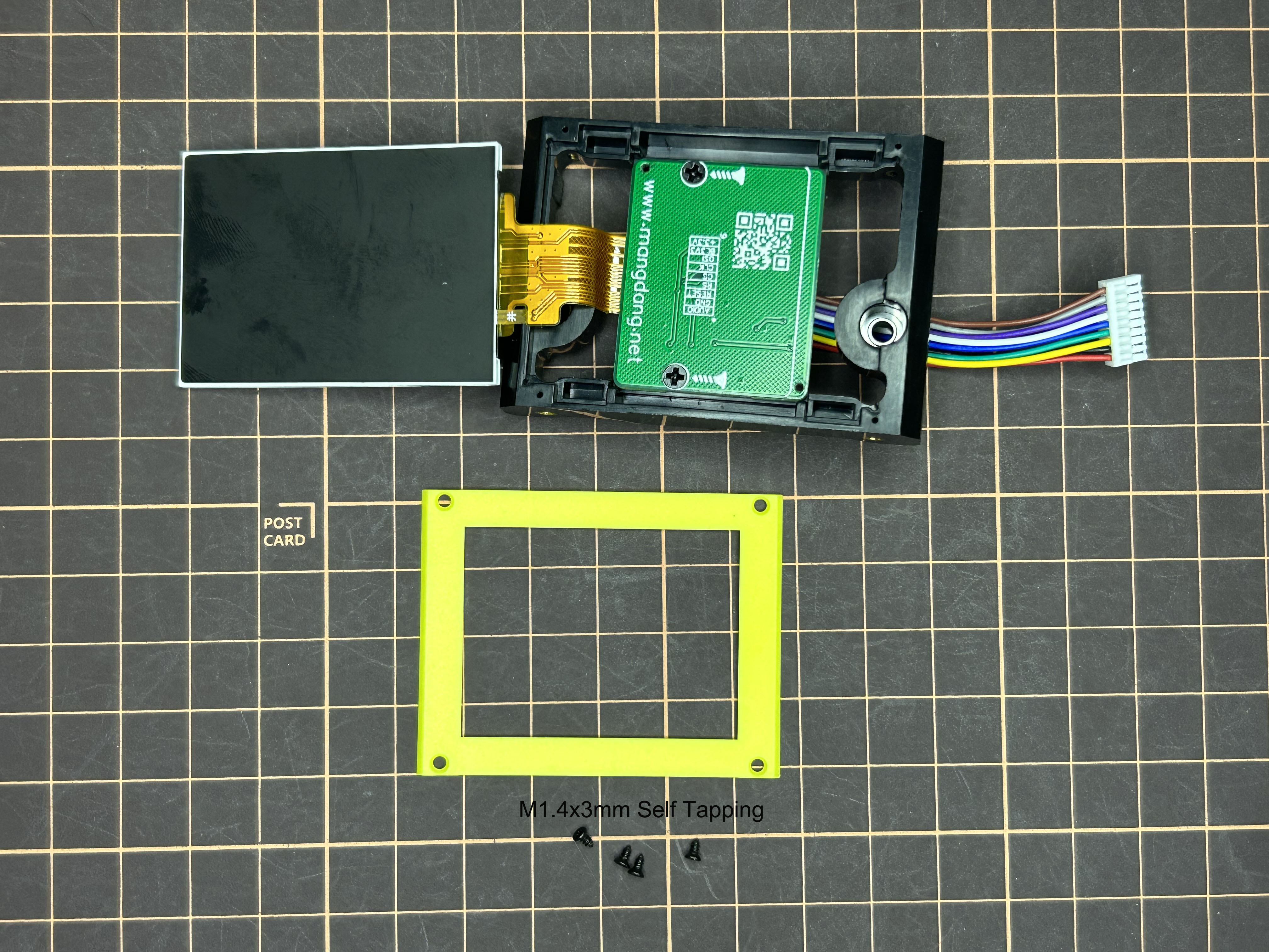
When attaching the display, you can use a stick to gently push the flexible FPC cable, so that it goes as far back as possible. Don't bend this FPC cable at 180 degrees.
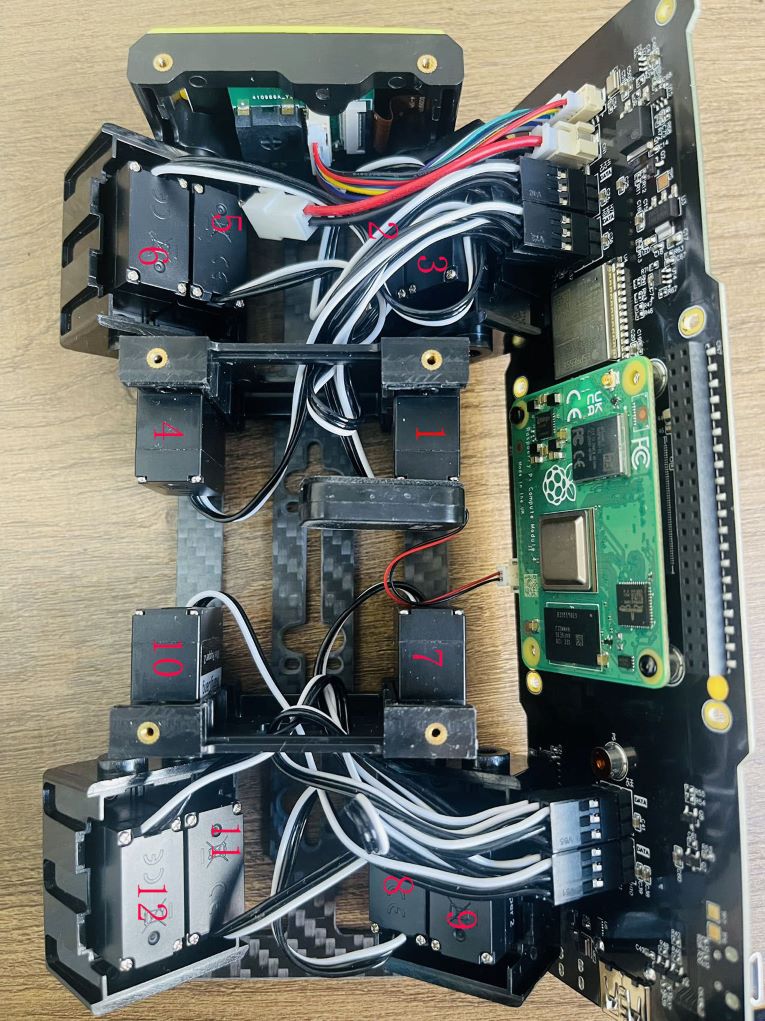
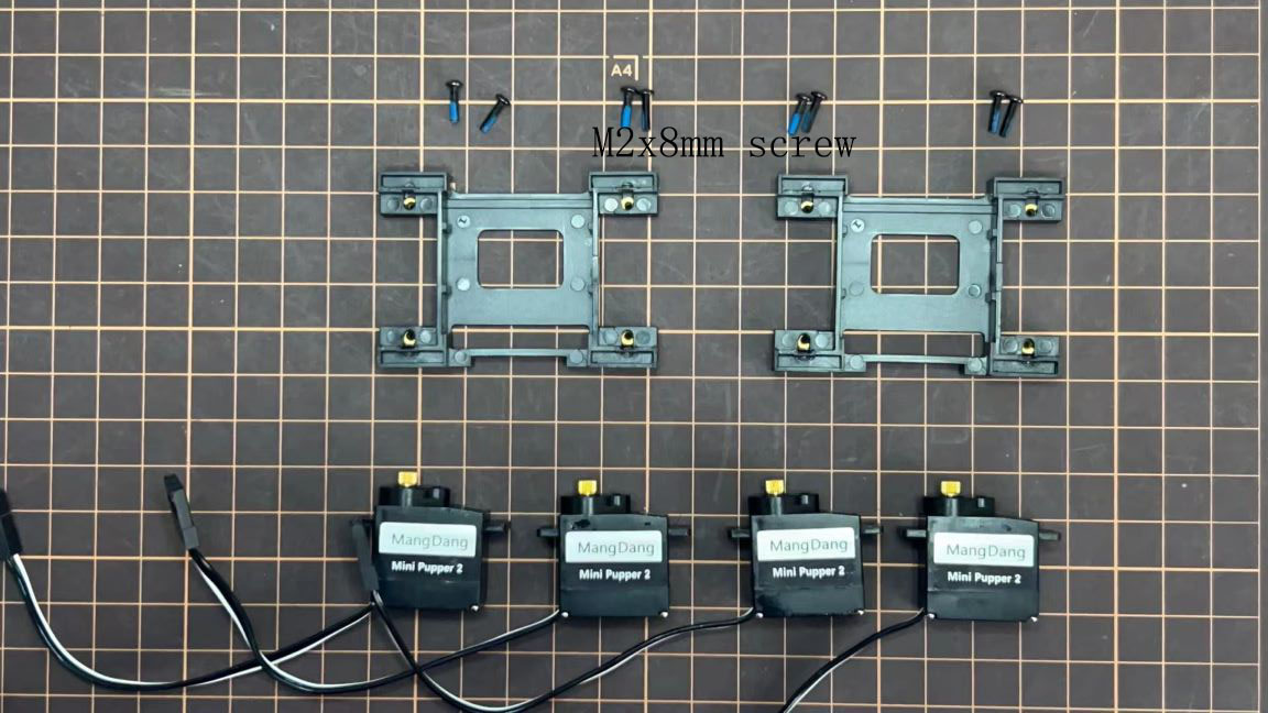
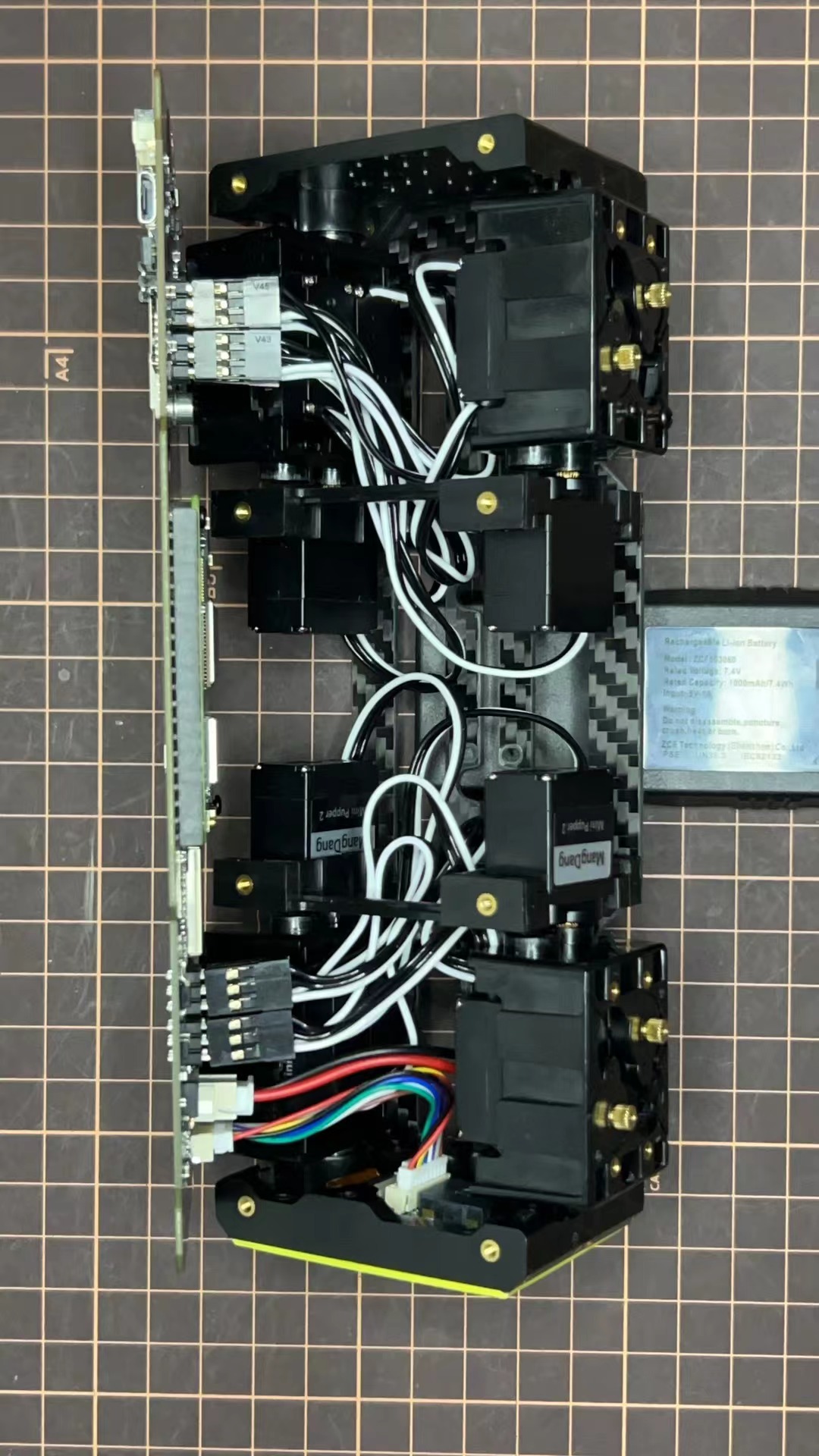
5. Body Frame and Hips Assembly
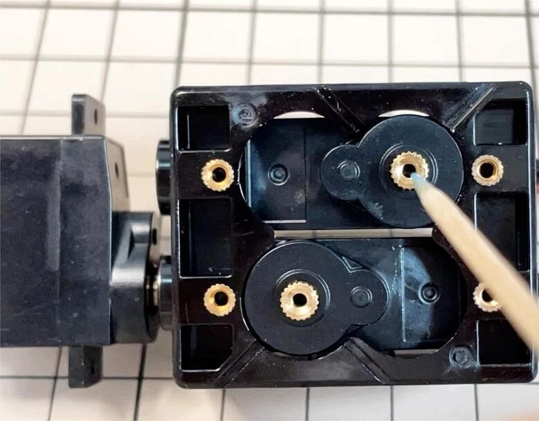
Refer to the top video for how to set servo ID.
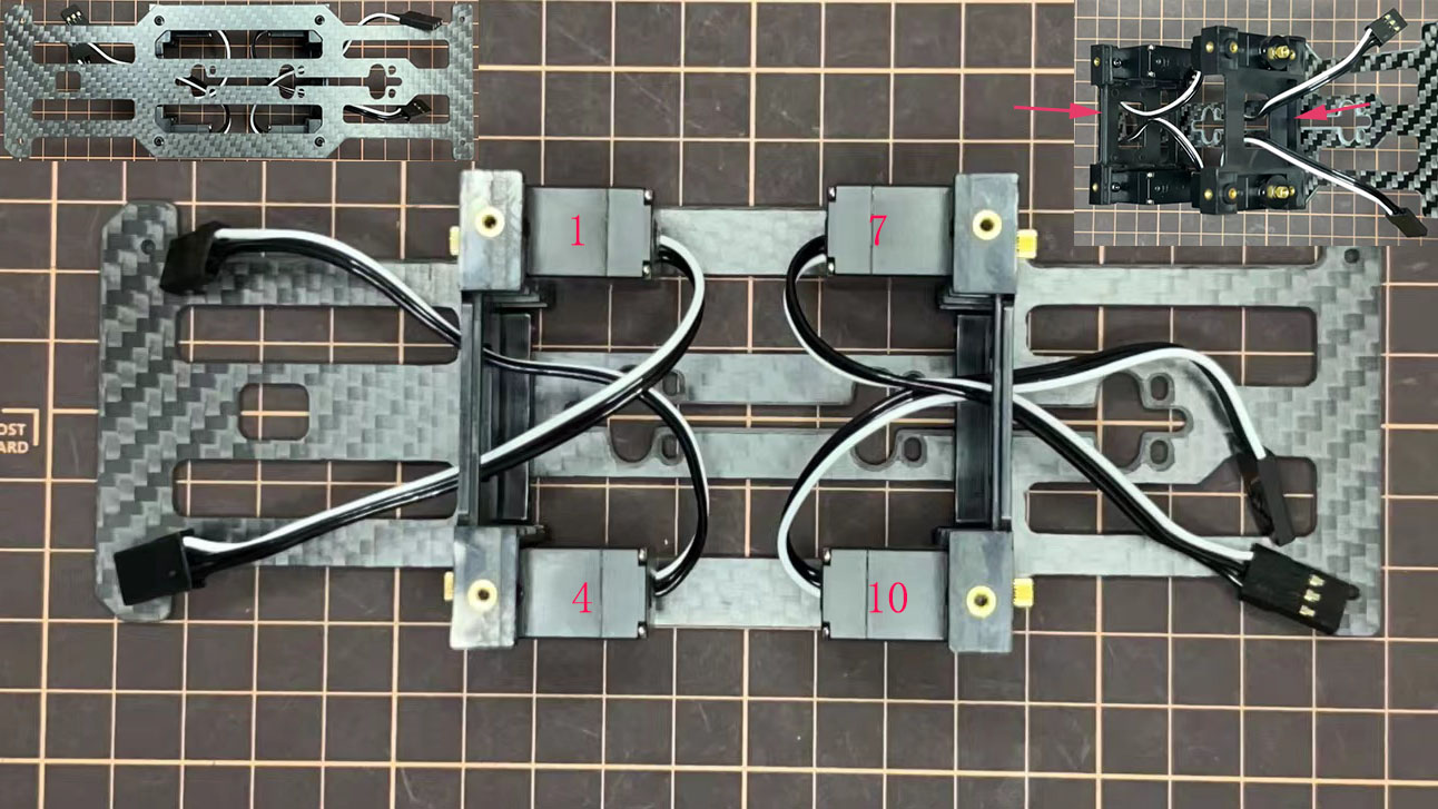
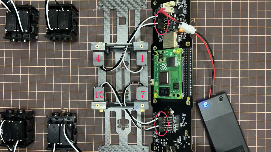
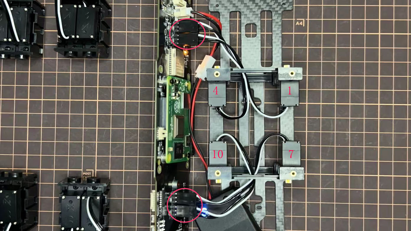
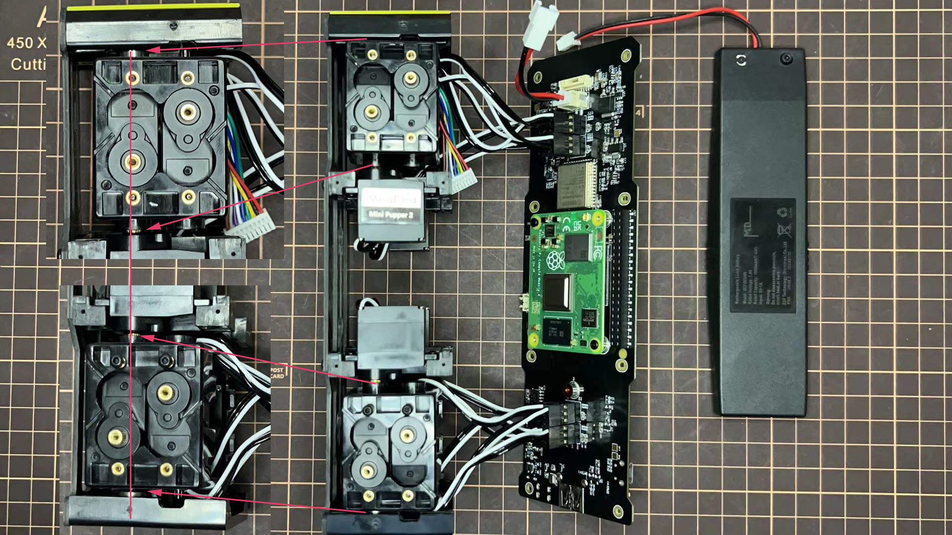
For the position of each servo, please refer to the below picture.
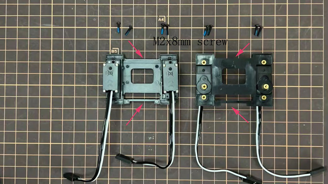
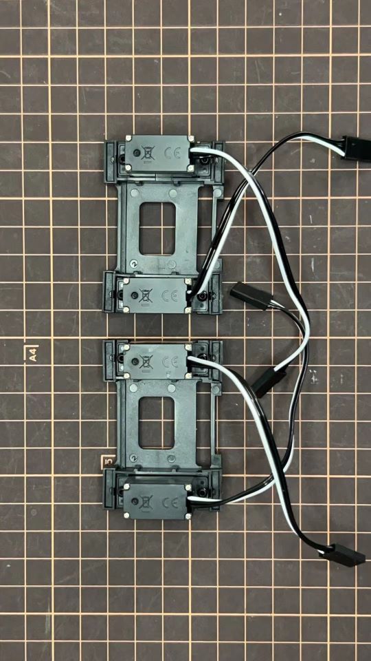
Step 5.1 Body center parts
Connect the No.1, 4, 7, 10 servos to the body center parts.
サーボケーブルにマスキングテープを貼って、サーボの数を書いておくと、後で楽です。
Pay attention to the center part direction.
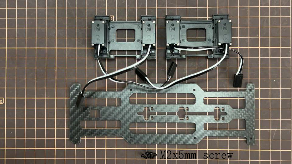
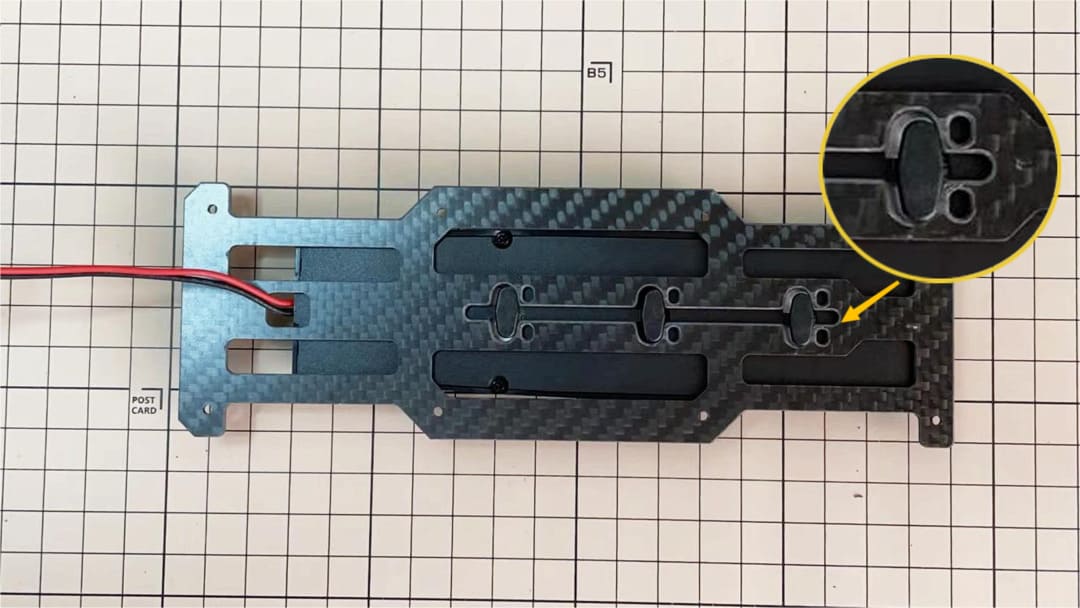
Connect the center parts to the bottom carbon fiber
前後の向きに気をつけましょう。
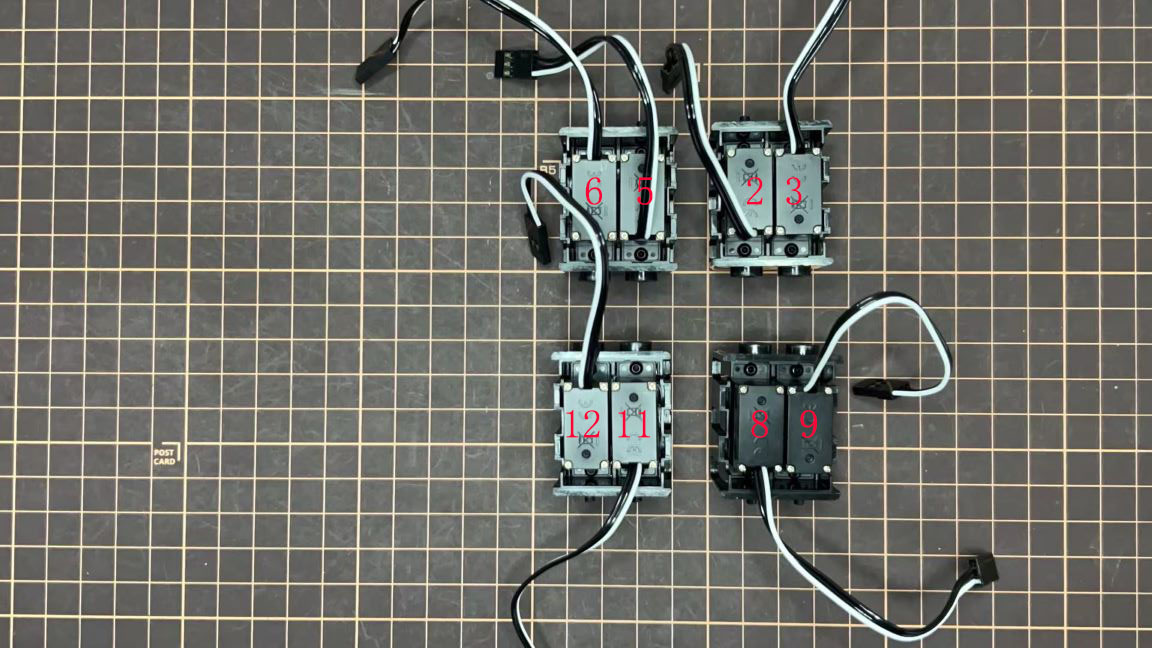
Step 5.2 Hip parts
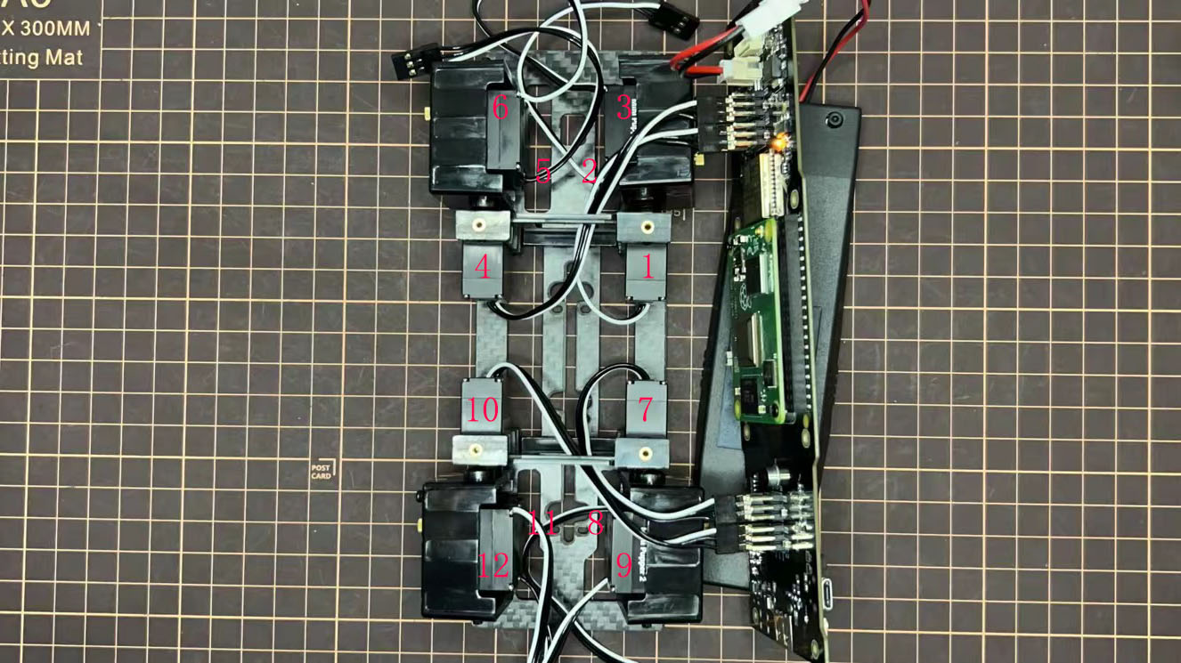
Assemble four hip parts, please refer to the servo positions.
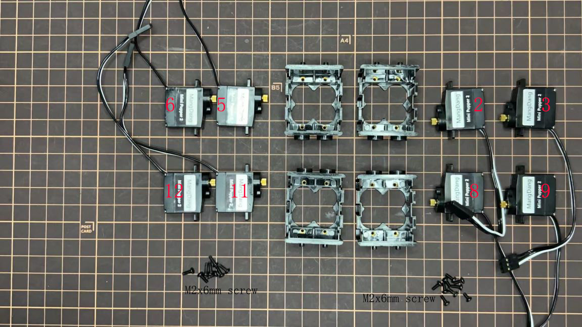
Ensure the No.1, 4, 7, 10 servos at the right position.
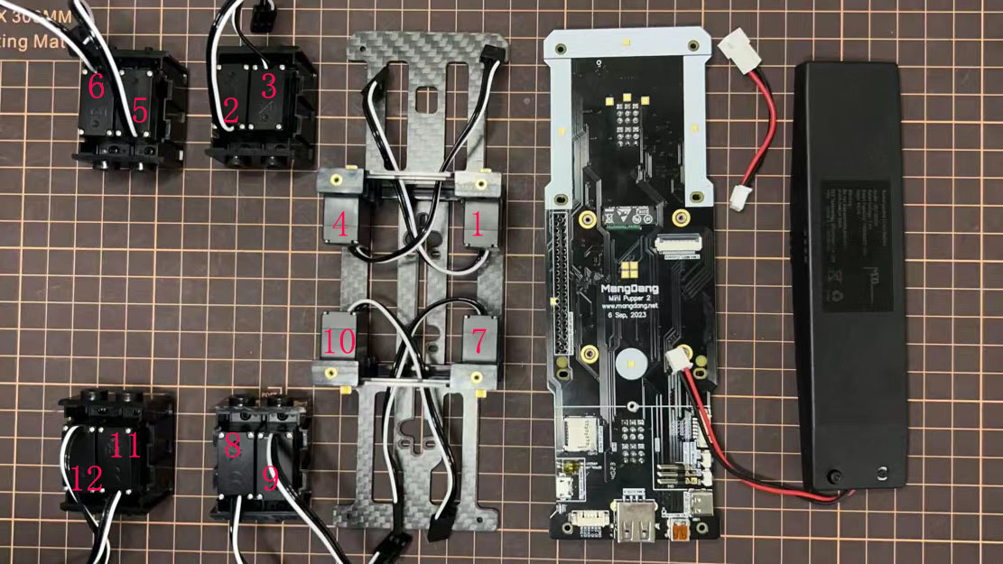
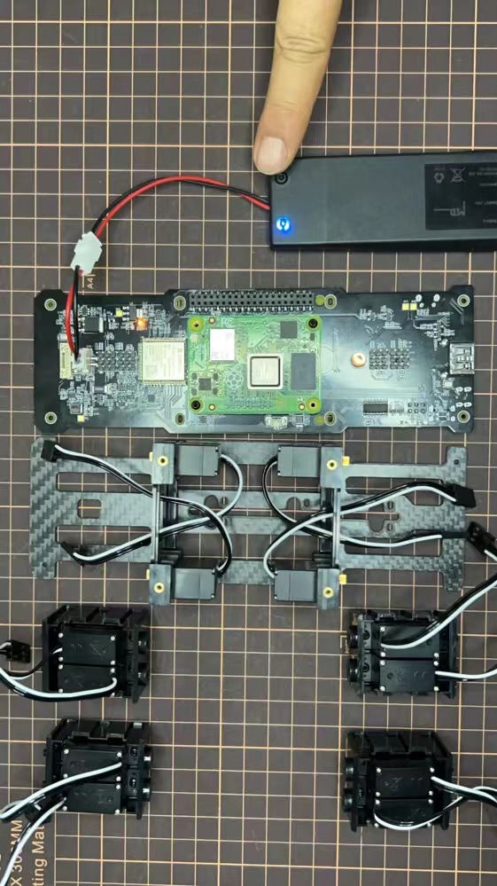
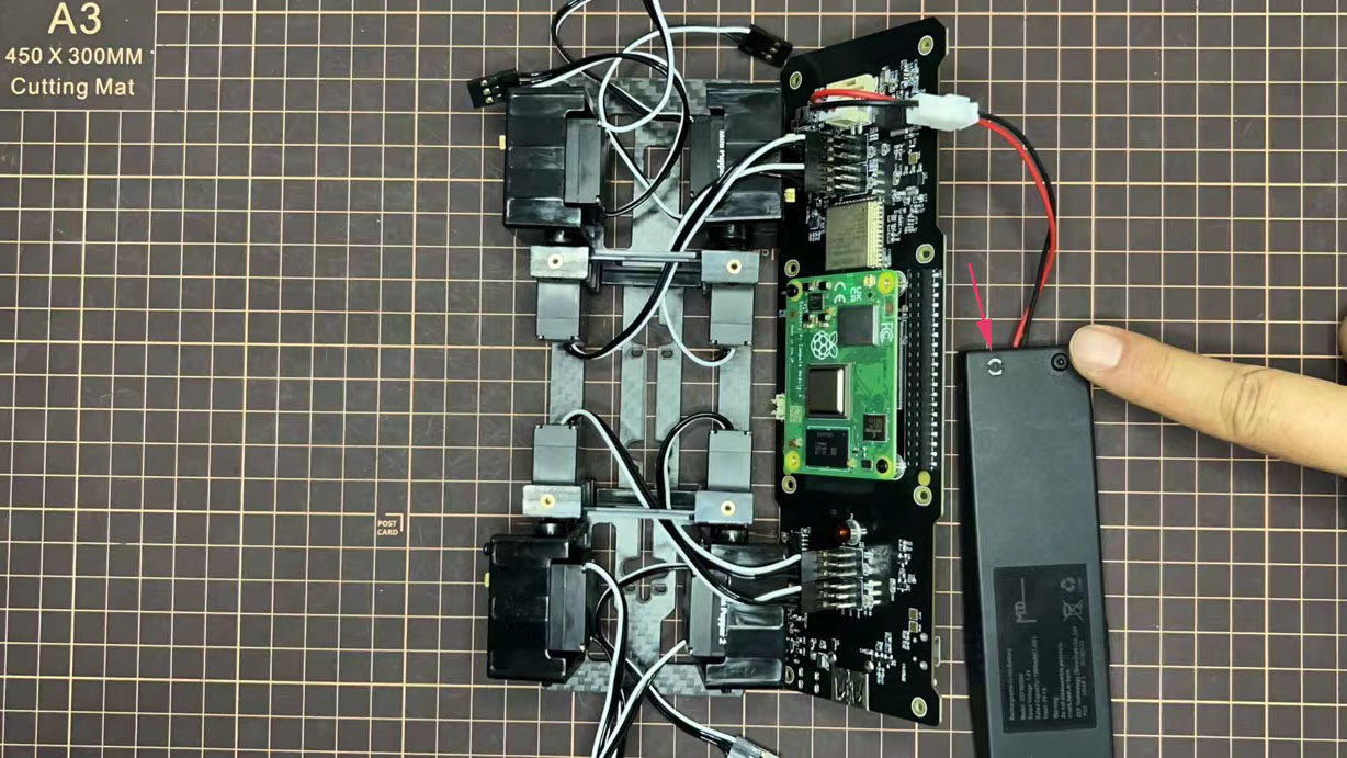
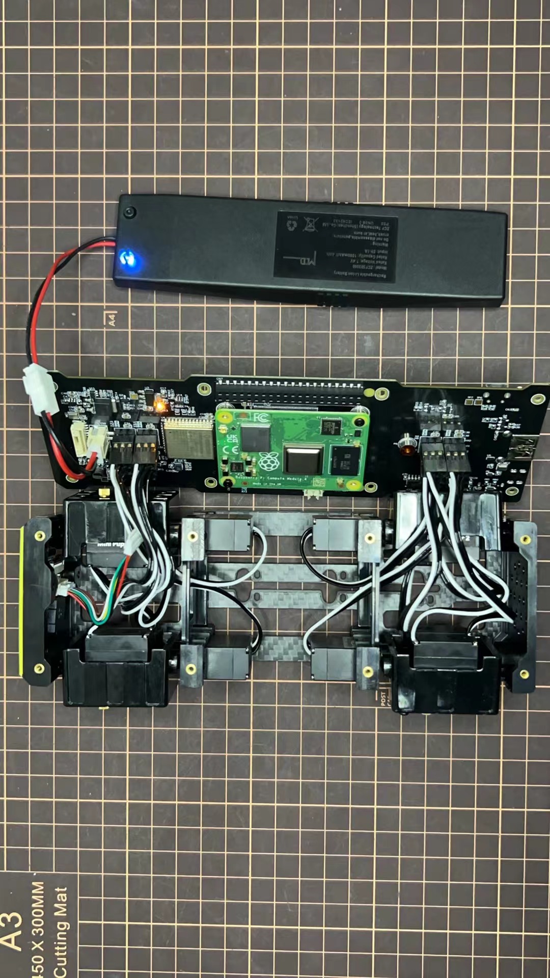
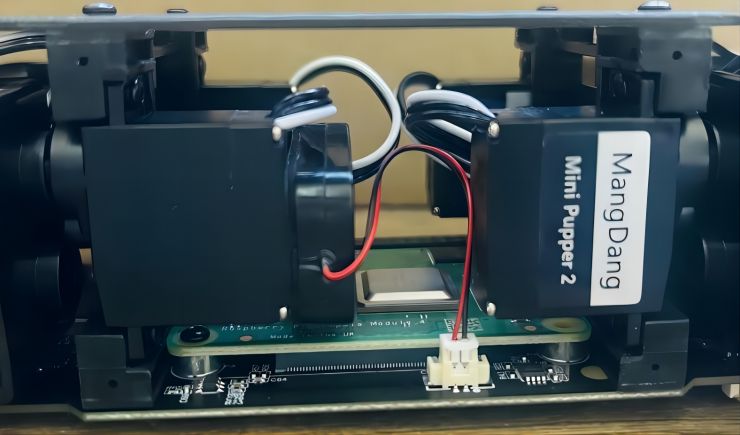
Use the custom cable to connect the battery to the top PCB board, and click the battery button for more than 3 seconds to boot up it.
Connect the servos to the top PCB board, please pay attention to the servo connector directions.
Connect the four hip parts to the body, please pay attention.
Don't power off the battery now.
Ensure all the servo positions are right.
Step 5.3 Front and back body parts
Power off the battery, and connect the front and back body parts.
Pay attention to the directions.
Power on the battery to check the hip parts all at their right positions, connect all the rest servos to the PCB board, and then power off the battery and go ahead.
Connect the LCD cable to the PCB board, make the servo cables clear.
Fix the top and bottom boards.
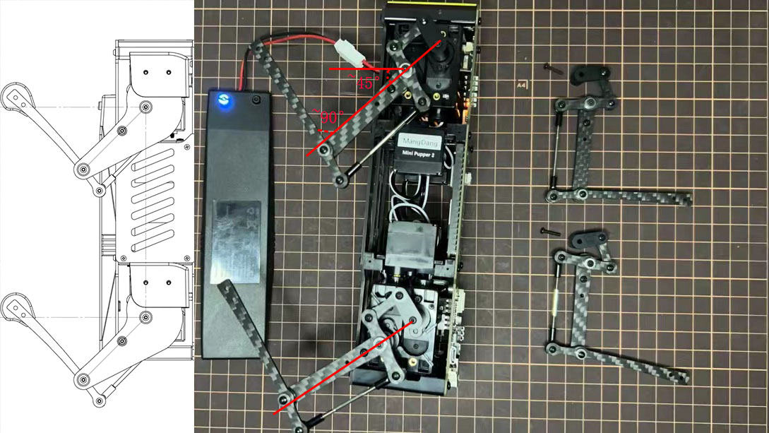
Step 5.4 Assemble four legs to the body
Pay attention to the theoretically best angles, it's better to meet the theoretically best angles as much as possible. But don't worry, we'll use the software to calibrate the angles later.
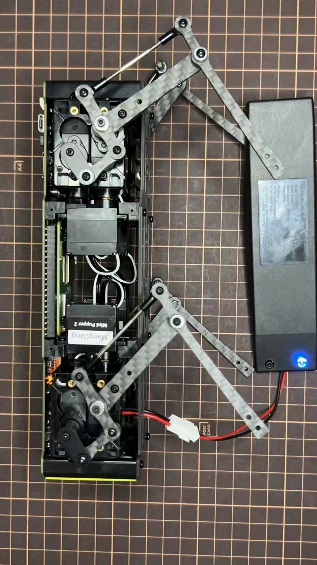
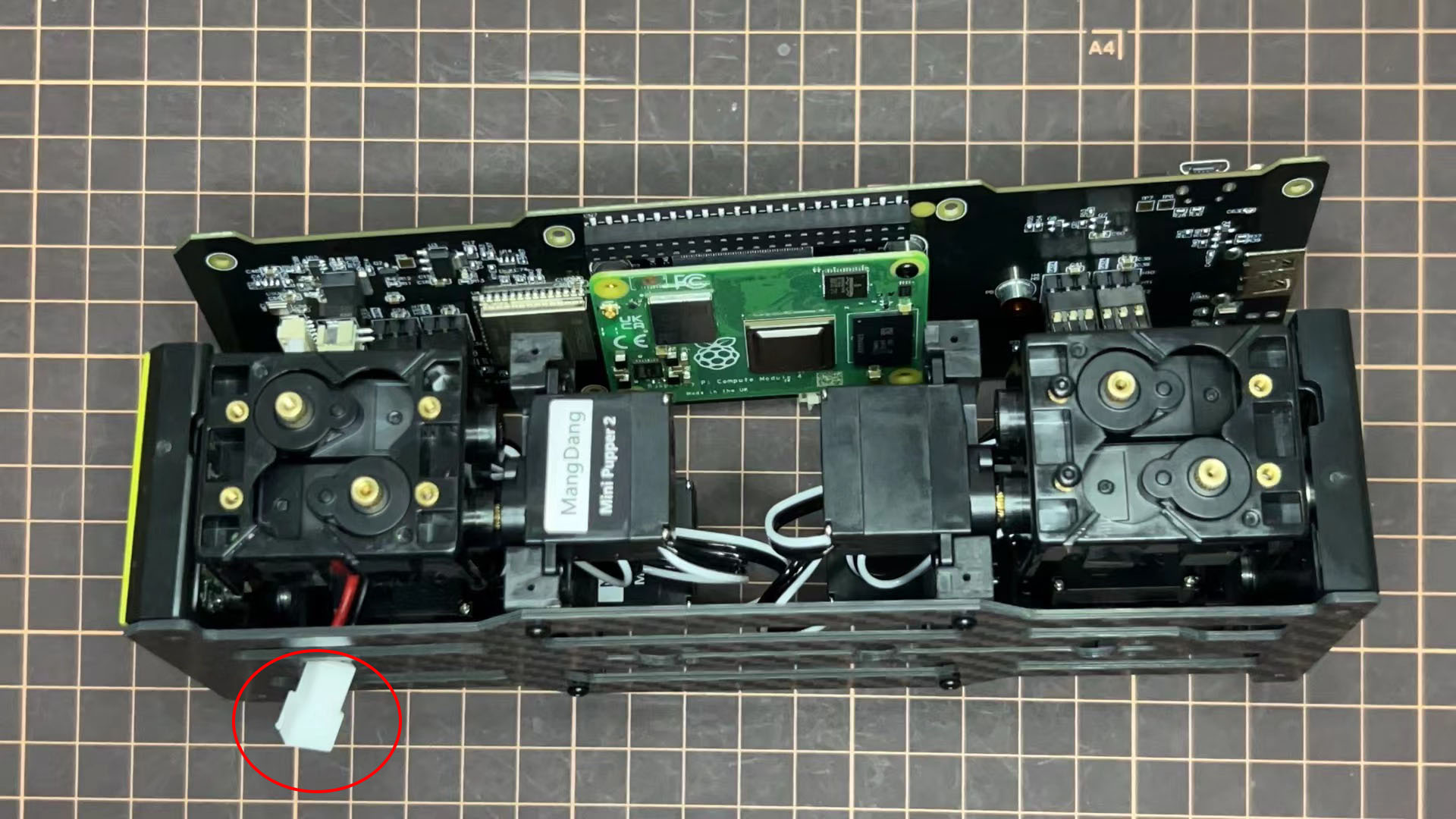
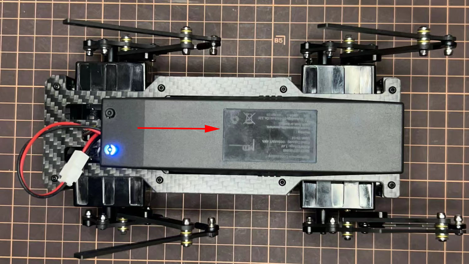
Step 5.5 Assemble the battery to the body
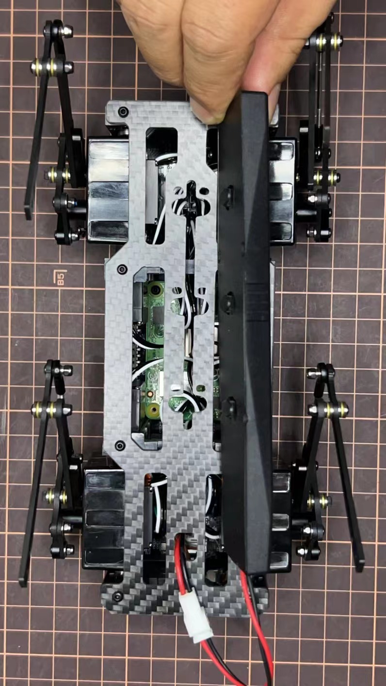
Slide the battery backward and secure it.

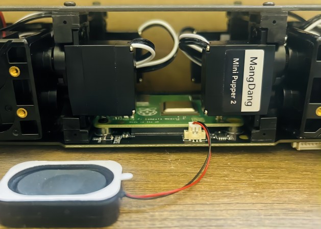
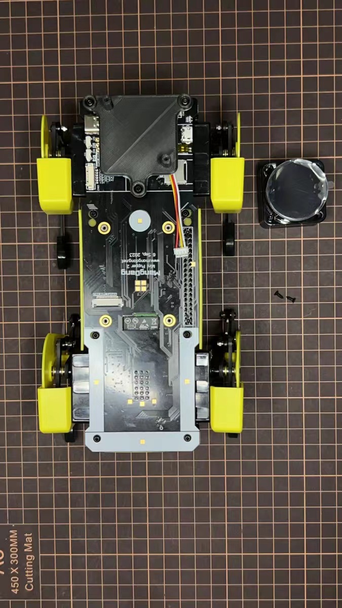
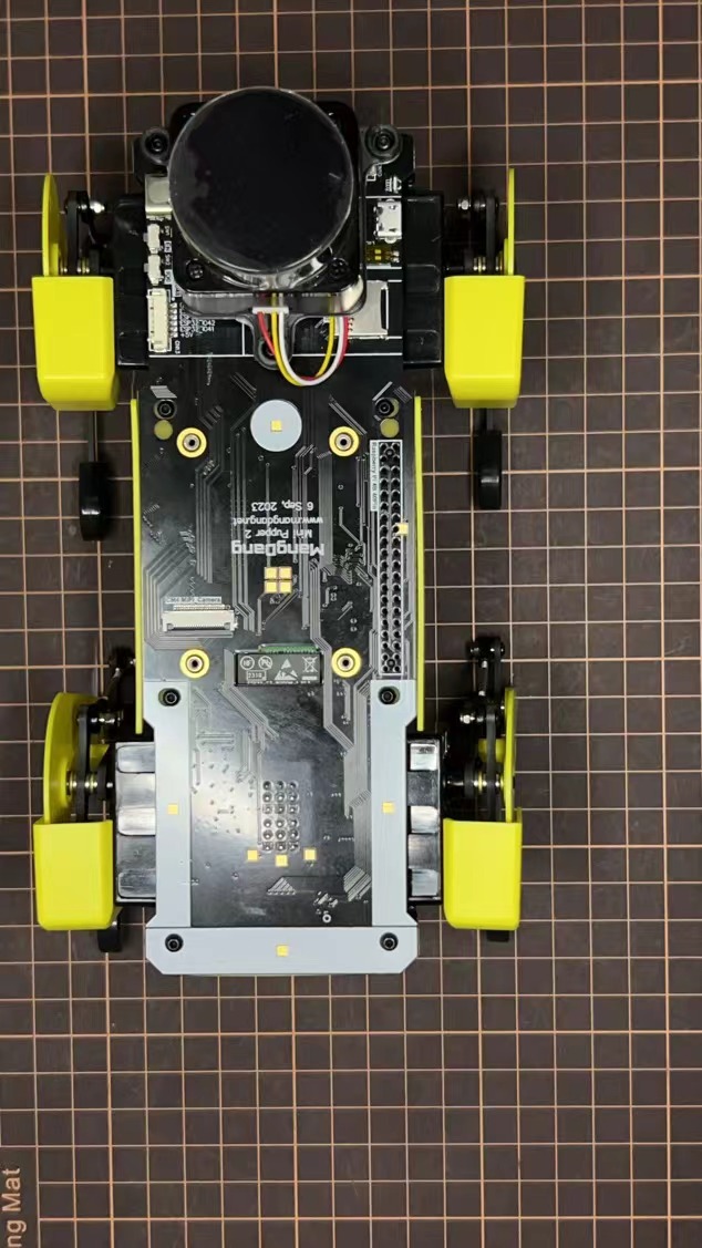
Step 5.6 Assemble the speaker
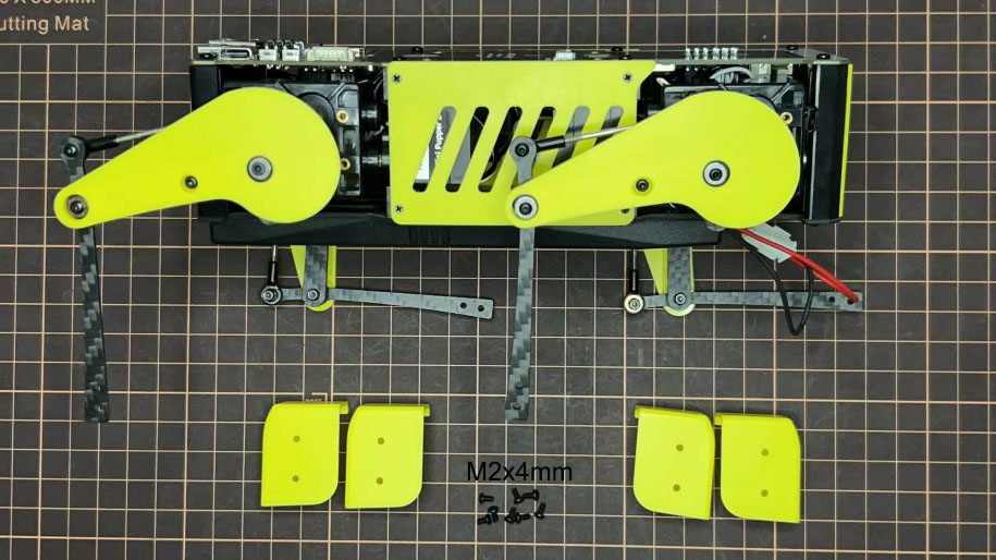
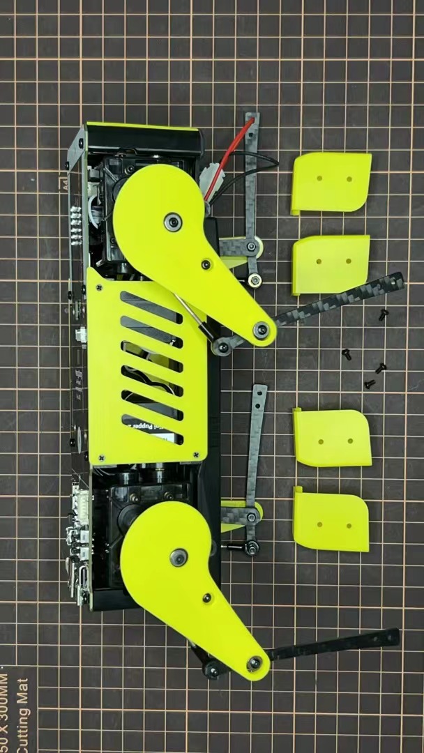
6. カバー部の組み立て
以下の動画をご参照ください。
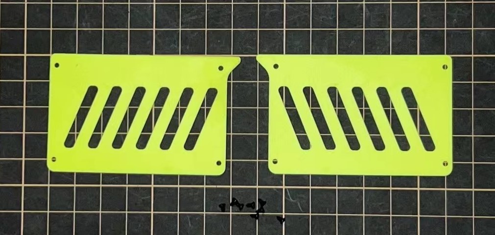
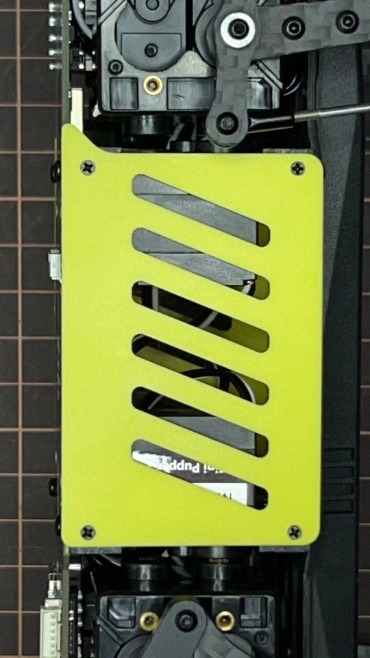
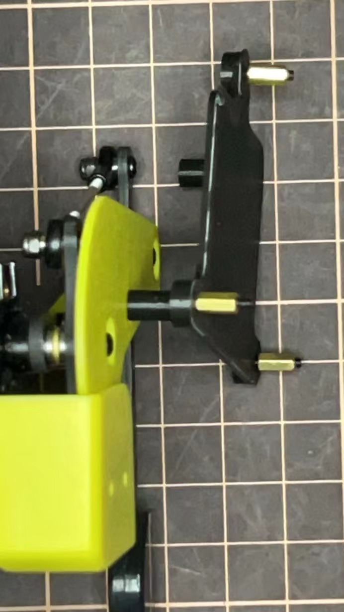
Step 6.1 本体のサイドパネル
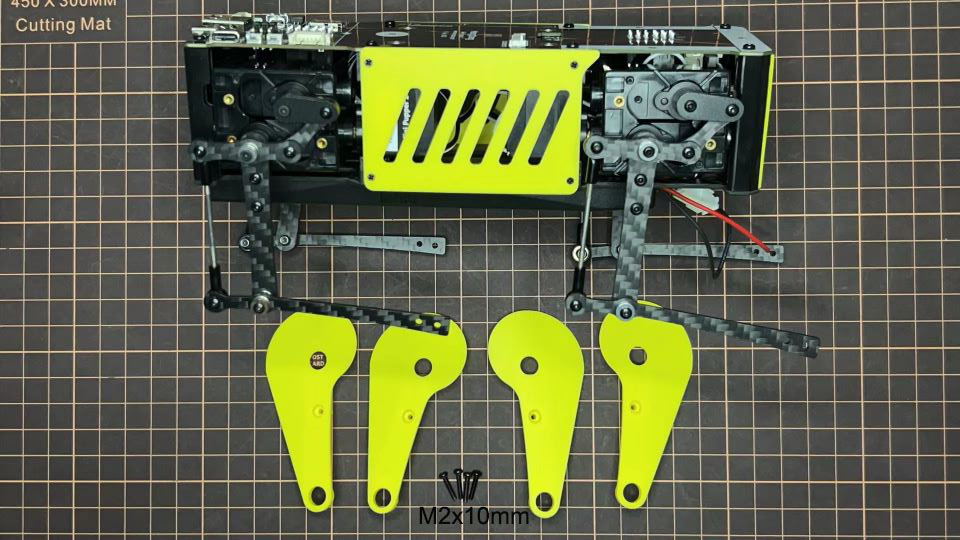
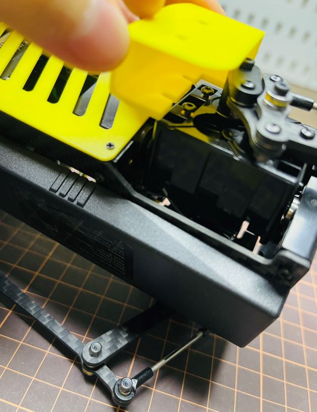
Step 6.2 もものカバー
M2x10mmのボルトを4本使用します。
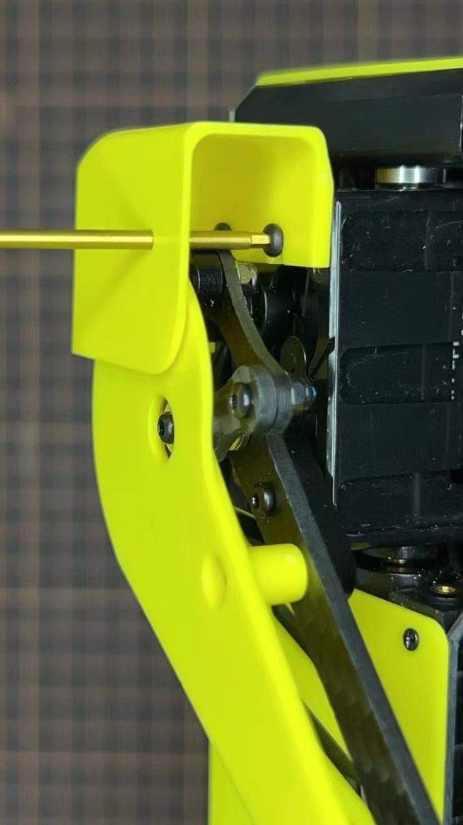
Step 6.3 足のカバ
先にボルトだけ挿し、その隙間に肩パーツを差し込みます。肩パーツの穴に2mm六角レンチを入れてボルトを締めます。
Step 6.4 Shoes
足元を取り付ける
Complete!
7. Add-On Assembly
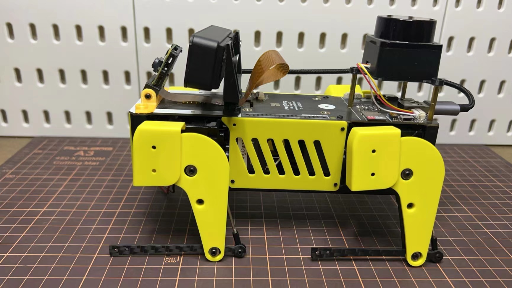
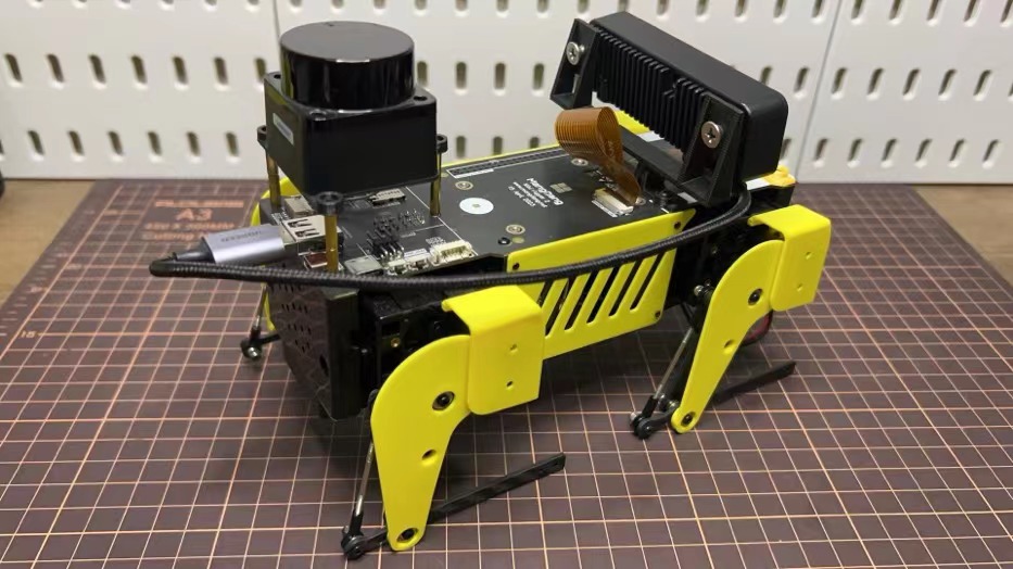
Step 7.1 Lidar
If you order the Lidar, the 3D-printed Lidar holder and custom cable will be shipped together. You can also print the holder by yourself using the Mini Pupper 2 STL files
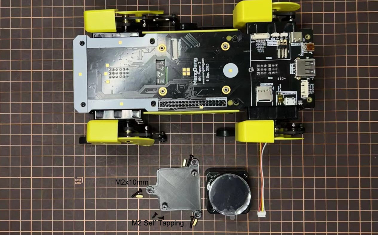
Connect the 3 holders to the 3D-printed part.
Connect the custom cable to the Lidar connector on the PCB board.

Fix the 3D-printed part on the PCB board.
Connect the custom cable to the Lidar module and fix it using the self-tapping screws.
Step 7.2 Camera
Mini Pupper 2 also supports the single Pi camera or OpenCV OAK-D-Lite camera module. You can also print the holder by yourself using the Mini Pupper 2 STL files